2 Part Question for Ladder Logic and Function Blocks

Foxtrot2050

Member
Join Date
Feb 2024
Location
OHIO
Posts
18
Good morning crew!

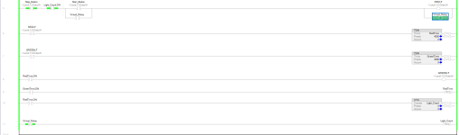
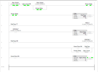
Ok my logic works but I am missing something. When the start button is pushed it should like the red light for 4sec then shut off. When the red light shuts off the green light is supposed to come on for 3 sec then shut off which triggers the red light to auto reset. This happens 5 times then shuts everything off. This all works but I am not sure how to shut off the red light without it ruining the whole system. I know I am close.

Part 2 = Once I get this working in Ladder Logic I need to make this into a function block program in Studio 5000. Any assistance would be great, I am still learning a lot about function block programming.

Thanks for any help I can get!
 

Attachments

  • 1.png
    1.png
    21.8 KB · Views: 37
Yes, you are close, only a couple of changes are needed to make this work.

[Update: I forgot to mention earlier that there is a bug in your code: the REDLT bit's value will be 1 for five cycles of 4000ms each, but the GREENLT bit's value will be 1 for only four cycles of 3000ms each.]

Ask yourself these questions:
  • During which scan cycles do I want the REDLT bit's value to be 0, but still have the system "running" i.e. the first rung (Start/Stop Circuit pattern see here) passing a True rung state to the OTE(s)?
  • What is the state of the bits in rest of the system during those scan cycles?
  • Is there a bit that has a unique value, either 0 or 1, during those scan cycles that could be used to write a 0 value into the REDLT?

Sidebar

Think about bits in memory; don't think about "lights" and "buttons. The PLC program scan does not write outputs (lights) and read inputs (buttons); the PLC program writes bits and reads bits in memory. The rest of the PLC, independent of the program scan, translates between bits in memory and the physical inputs and outputs.

A request about how to post images1.png
 
Last edited:
I am still confused, when I put in the rung that if Greentime.TT is engaged I thought it would stop the light but this isn't the case. In a normal setting I would latch and unlatch but I am required to use the virtual bit. Anymore guidance or a helping hand would be appreciated.
 
Here is a suggestion for a path to take:
  • Take out a piece of paper and draw a "contact diagram" i.e. draw what the states of the various bits are, up for 1, down for 0, over time, like the diagram at the bottom of this page. At a minimum, do the virtual_relay, redlt, greenlt, /DN bits, /TT bits.
  • Draw what you are seeing now, and then in a different color draw the behavior you want to see.
Look at that and see if anything stands out to you.
 
Le me give you two suggestions for using timers.

  1. If you want something to happen FOR a period of time, then you would be best served to use the .TT bit. If you want something to happen AFTER a period of time, then you would use the .DN bit. Do you want the Red Light to turn on FOR four seconds, or AFTER four seconds? Do you want the Green Light to turn on FOR three seconds, or AFTER three seconds? Using the .TT for the lights will be much easier and more logical.

  2. Use your pushbutton to start/stop the timer. Use the timer status bits to control the outputs.

  3. Bonus suggestion...if you are trying to turn something ON AFTER a period of a time, use the Timer On-Delay and the DN bit. If you are trying to turn something OFF AFTER a period of time, use the Timer Off-Delay and the DN bit. If trying to make something happen FOR a period of time, either time can be used, though most stick with the TON.
OG
 
@drbitboy here is my final result. I have very little "ego" I am still early in the learning stage but I appreciate your drive to make me think about my logic.
 

Attachments

  • Screen.png
    Screen.png
    35.8 KB · Views: 23
@drbitboy here is my final result. I have very little "ego" I am still early in the learning stage but I appreciate your drive to make me think about my logic.
That is excellent.

One or two things to think about:
  • It would not hurt to get in the practice of adding comments. There are many guides to code comment online, but the primary task is to describe the process, not the code.
    • This is not a perfect example, but a Rung 2 comment such as
      • "Turn on Red Light while first timer is time and has not expired"
    • is better than
      • "Write a 1 to the REDLT output value when the RedTimer.TT bit value is 1."
  • You have each rung doing one thing, and one thing only (for the most part). Again, this is excellent and is generally considered a best practice as it makes the code easier to understand, which is the most important aspect coding for industry (see this video about Rule 1).
  • The RESet instruction is great. Note that another common way to implement a repeating timer is to use an XIO instruction with the .DN bit feeding the timer (see here and the image below) in this case this would mean adding an XIO GreenTimer.DN in series with the XIC Virtual_Relayon Rung 2.
    • That one instruction eliminates the upper branch (XIC GreenTimer.DN RES RetTimer on Rung 5.
    • I only bring this up because one of the things I think I see in new programmers is that they tend to thing in positive logic and miss the opportunities that negative logic provides.
      • That does not appear to be the case with you but it is usually a good exercise to flip the logic to see what is possible and if more clarity is possible (cf. Rule 1 above).
    • Caveat: in some PLC brands, this approach will not work (for a single repeating timer); see the last paragraph before "Further Information" on this page.
  • Note that the order of the counter reset on Rung 5 and the counter Rung 6 is critical; the code would not work if those rungs were reversed. (update whoops that is not true, I was thinking it was XIC Light_Count.DN RES Light_Count).
    • An alternative to using the RESet instruction is to clear the counter accumulator value (Light_Count.ACC) to 0.
      • This is sometimes preferable.
      • It would not matter in this case since the Green_Time.DN bit is a one-shot, but ...
      • If the rung feeding the CTU instruction is still True* on the next CTU evaluation after the RESet,
        • then that will generate a false count (from 0 to 1) in the CTU,
        • because the RESet clears the CU (CountUp) bit value to 0,
        • which CU bit is used to detect the rising edge of the input rung that triggers and CTU increment.
        • See here; note the first decision block, <.CT is True>, which is the rising edge detector.
  • Something to think about on Rungs 3 and 4:
    • These rungs have essentially the same state
      • i.e. the RedTime.DN and the GREENLT bits are functionally synonymous, although you have offset the start of the green timer by one scan cycle in time, perhaps intentionally,
      • and there is absolutely nothing wrong with evaluating an output bit in a contact; if anything it shows a useful and ruthless disregard for the meaning of bits when their value is what is important.
    • So it might be worthwhile driving both outputs on the same rung
      • i.e. XIC RedTime.DN BST OTE GREENLT NXB TON RedTime 3000 0 BND
    • Even if you put that on two rungs, both starting with XIC RedTime.DN,
      • I think this expresses the logic more clearly
        • I.e. the timers' inter-relationship, that the green timer is cascaded from the red timer expiry,
      • but that is only an opinion,
        • and there is certainly an argument to be made that having the green light state drive the green timer expresses the purpose of the green timer better.
* e.g. from a button press or encoder pulse that is being counted and that is sustained for tens or hundreds of milliseconds and multiple scan cycles

Flasher-Two-Timer-Variant.png
 
One of the interesting aspects of logic (to me at least) is that their is often more than one way of accomplishing a task. I always told my students, if it works, then it's right. There may be other ways of doing it, and some may make more sense, others may be more efficient, but as long as it works, it's right. The real test is can you explain it to someone else. And that is where the whole documentation thing drbitboy mentions comes into play. Can someone look at the logic, read the comments, and understand how it works.

I know you had also asked about solving this using function blocks. While it can certainly be done, to me, it is the wrong tool for the job. Function blocks really aren't great for solving discrete logic like this. Once you get started with that logic, show us what you have come up with, and we will help guide you to a solution.

OG
 
That is excellent.

One or two things to think about:
  • It would not hurt to get in the practice of adding comments. There are many guides to code comment online, but the primary task is to describe the process, not the code.
    • This is not a perfect example, but a Rung 2 comment such as
      • "Turn on Red Light while first timer is time and has not expired"
    • is better than
      • "Write a 1 to the REDLT output value when the RedTimer.TT bit value is 1."
  • You have each rung doing one thing, and one thing only (for the most part). Again, this is excellent and is generally considered a best practice as it makes the code easier to understand, which is the most important aspect coding for industry (see this video about Rule 1).
  • The RESet instruction is great. Note that another common way to implement a repeating timer is to use an XIO instruction with the .DN bit feeding the timer (see here and the image below) in this case this would mean adding an XIO GreenTimer.DN in series with the XIC Virtual_Relayon Rung 2.
    • That one instruction eliminates the upper branch (XIC GreenTimer.DN RES RetTimer on Rung 5.
    • I only bring this up because one of the things I think I see in new programmers is that they tend to thing in positive logic and miss the opportunities that negative logic provides.
      • That does not appear to be the case with you but it is usually a good exercise to flip the logic to see what is possible and if more clarity is possible (cf. Rule 1 above).
    • Caveat: in some PLC brands, this approach will not work (for a single repeating timer); see the last paragraph before "Further Information" on this page.
  • Note that the order of the counter reset on Rung 5 and the counter Rung 6 is critical; the code would not work if those rungs were reversed. (update whoops that is not true, I was thinking it was XIC Light_Count.DN RES Light_Count).
    • An alternative to using the RESet instruction is to clear the counter accumulator value (Light_Count.ACC) to 0.
      • This is sometimes preferable.
      • It would not matter in this case since the Green_Time.DN bit is a one-shot, but ...
      • If the rung feeding the CTU instruction is still True* on the next CTU evaluation after the RESet,
        • then that will generate a false count (from 0 to 1) in the CTU,
        • because the RESet clears the CU (CountUp) bit value to 0,
        • which CU bit is used to detect the rising edge of the input rung that triggers and CTU increment.
        • See here; note the first decision block, <.CT is True>, which is the rising edge detector.
  • Something to think about on Rungs 3 and 4:
    • These rungs have essentially the same state
      • i.e. the RedTime.DN and the GREENLT bits are functionally synonymous, although you have offset the start of the green timer by one scan cycle in time, perhaps intentionally,
      • and there is absolutely nothing wrong with evaluating an output bit in a contact; if anything it shows a useful and ruthless disregard for the meaning of bits when their value is what is important.
    • So it might be worthwhile driving both outputs on the same rung
      • i.e. XIC RedTime.DN BST OTE GREENLT NXB TON RedTime 3000 0 BND
    • Even if you put that on two rungs, both starting with XIC RedTime.DN,
      • I think this expresses the logic more clearly
        • I.e. the timers' inter-relationship, that the green timer is cascaded from the red timer expiry,
      • but that is only an opinion,
        • and there is certainly an argument to be made that having the green light state drive the green timer expresses the purpose of the green timer better.
* e.g. from a button press or encoder pulse that is being counted and that is sustained for tens or hundreds of milliseconds and multiple scan cycles

Flasher-Two-Timer-Variant.png
Wow. Yes, very good information here. I will be adding this to my brain bank for sure. For some reason I forgot that putting the .DN bit would essentially reset the timer also. Good call, really appreciate this information.
 
+1 for what @Operaghost said, esepcially about more than one way to solve it.

In that spirit, here is one single-timer approach; personally, I find a single timer and an accumulator comparison to be more clear than a cascading timers, but that's just me (i.e. I read "4s red and 3s green" and immediately think "7s cycle").

That said, you would never put this in a real process, because that first rung, even though it works, is a hot mess from a clarity standpoint, and spreading things out, where each rung does one thing like you did, is more clear.
 

Attachments

  • Untitled.png
    Untitled.png
    31.4 KB · Views: 5

Similar Topics

Concept of the system (Sketch of system attached) **I am blessed to be a member of this community, thanks in advance** System is a chain...
Replies
8
Views
3,004
Looking for a brief explanation for the NEMA MG-1 Part 31 standard for the actual voltage values. In reading many articles I have seen 1488Vp...
Replies
0
Views
1,407
I have a colleague who has said that OSHA considers motion slower than 10in/sec safe and that you don't have to guard it. I have never seen this...
Replies
10
Views
3,853
Hello Guys, I’m curious how the pros on this board would program in the following situation. Take the case where it is required that the machine...
Replies
5
Views
2,280
Ok, got some good feeback on the DC to AC issue its been a great resource!! This next question ties in with that same project. I will (probably)...
Replies
5
Views
2,436
Back
Top Bottom