Hi there,
PLC in question: 240VAC Omron CP1E-NA20DR-A
Features: 12 inputs – 2 of which analogue, 8 outputs – 1 of which analogue
My question is in regards to using an analogue input.
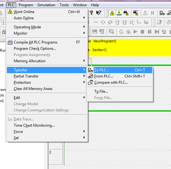
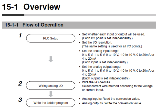
Starting with the manual procedure for installing an analogue input:
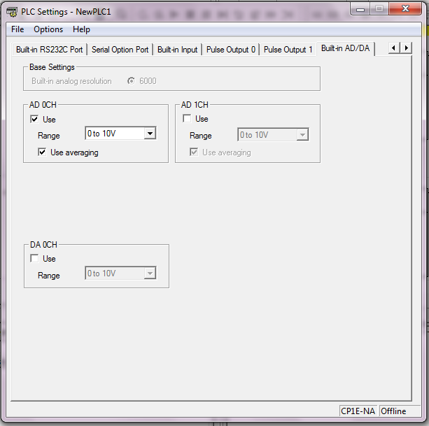
1) So I began with setting up the analogue input; AD 0CH, Range 0 – 10V, Use averaging (as suggested):
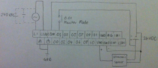
2) Wire up device, this is my current wiring diagram:
3) Write the ladder diagram, I have a more sophisticated program prepared but I thought I’d simplify things in order to check everything is working properly:
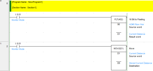
In this program I am trying to read an analogue input from an ultrasonic sensor with a 0 – 10 VDC output (AD#0 Raw Hex) and convert it to floating point so I can do additional arithmetic. The source word address should be correct as it specifies in the manual that AD0 data is stored in CIO 90. Then I want to store this initial reading in memory D5.
This is what the program looks like when it is running:
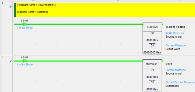
As you can see the source word is 0000 Hex but it should have a reading between #0000 and #FFFF. I have checked the ultrasonic sensors output with a multimeter and I do get a reading between 0 and 10.25 VDC depending on the distance.
I have tried a number of things to make this work but I’m out of ideas. If you have any suggestions as to what’s going on and why this is not working please let me know.
Thanks in advance
PLC in question: 240VAC Omron CP1E-NA20DR-A
Features: 12 inputs – 2 of which analogue, 8 outputs – 1 of which analogue
My question is in regards to using an analogue input.
Starting with the manual procedure for installing an analogue input:
1) So I began with setting up the analogue input; AD 0CH, Range 0 – 10V, Use averaging (as suggested):
2) Wire up device, this is my current wiring diagram:
3) Write the ladder diagram, I have a more sophisticated program prepared but I thought I’d simplify things in order to check everything is working properly:
In this program I am trying to read an analogue input from an ultrasonic sensor with a 0 – 10 VDC output (AD#0 Raw Hex) and convert it to floating point so I can do additional arithmetic. The source word address should be correct as it specifies in the manual that AD0 data is stored in CIO 90. Then I want to store this initial reading in memory D5.
This is what the program looks like when it is running:
As you can see the source word is 0000 Hex but it should have a reading between #0000 and #FFFF. I have checked the ultrasonic sensors output with a multimeter and I do get a reading between 0 and 10.25 VDC depending on the distance.
I have tried a number of things to make this work but I’m out of ideas. If you have any suggestions as to what’s going on and why this is not working please let me know.
Thanks in advance