I'm working on interfacing a MicroLogix 1000 and a PanelView C600.
I've scoured the internet trying to find specific examples or tutorials without success. I've tried a combination of settings found scattered in various documents/newsgroups/articles, etc, but still not able to make it work.
So, here's what I've done. I've used the KISS approach to just have the PV (when ON button is pushed of course) set the true bit on an input contact in a basic ladder program. I've included all the relevant screenshots below.
Hardware used:
Assumptions:
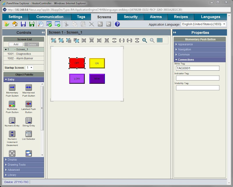
The screen has just 4 buttons (let's ignore the bottom 2 for now), with the first top 2 supposedly setting the bits on those referenced inputs (OFF button Write Tag = "TAG0001" while ON button Write Tag = "TAG0002"):
These are the Tags that reference the inputs:

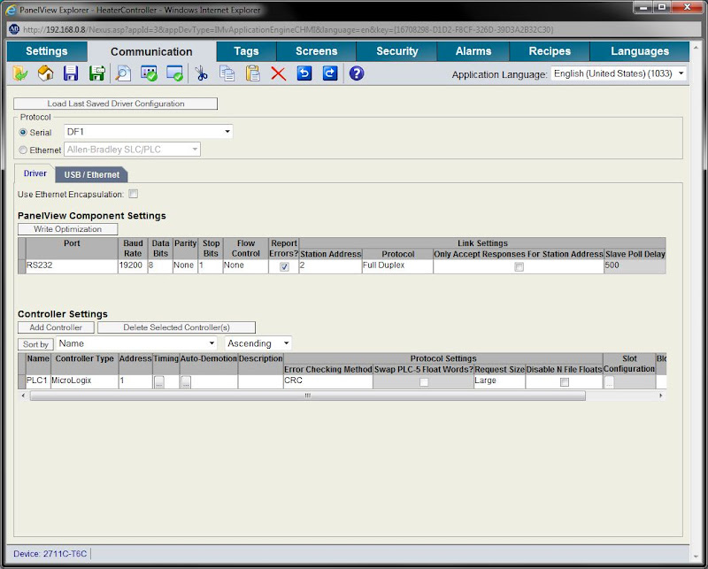
Here are the PV app communication settings:
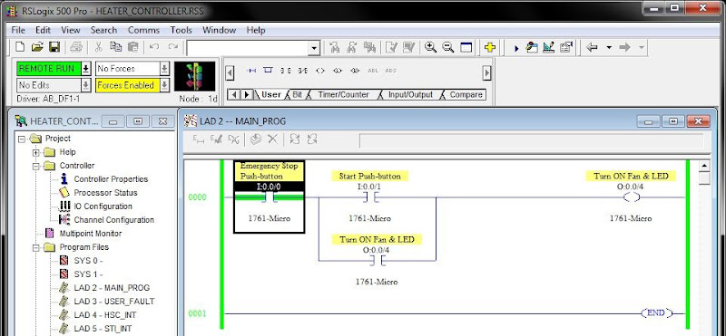
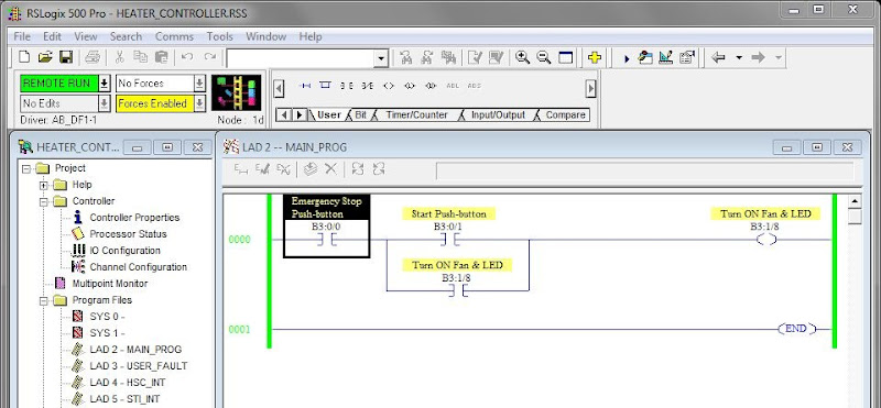
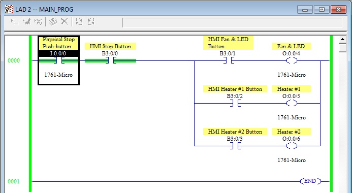
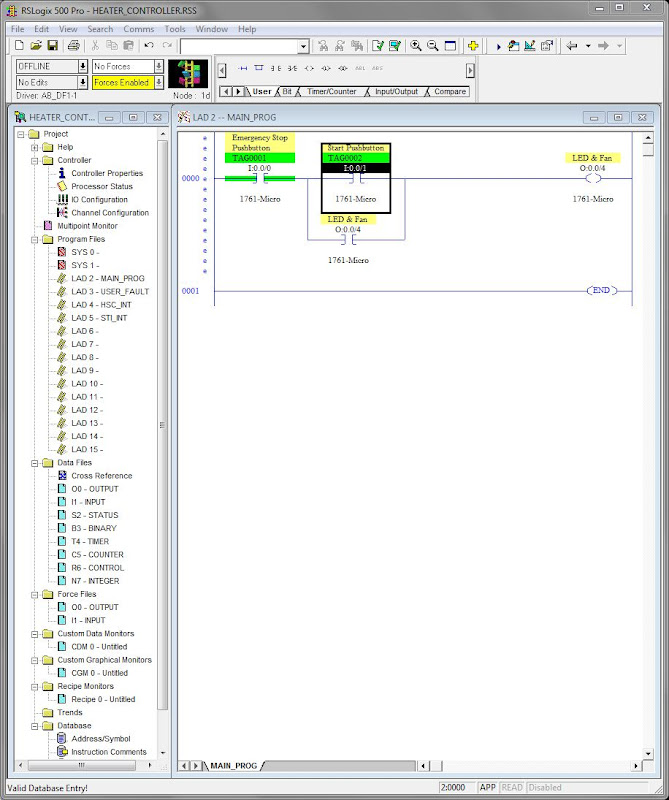
Here's a basic ladder program that just turns an output. Note that the inputs have the symbol set to match those PV tags:
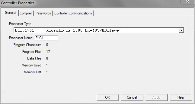
These are the Controller properties that match the name referenced in the PV tags:
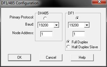
And finally, here are the Channel Configuration settings:
If you could point me in the right direction, I would greatly appreciate it!!!
Thanks in advance,
sb
I've scoured the internet trying to find specific examples or tutorials without success. I've tried a combination of settings found scattered in various documents/newsgroups/articles, etc, but still not able to make it work.
So, here's what I've done. I've used the KISS approach to just have the PV (when ON button is pushed of course) set the true bit on an input contact in a basic ladder program. I've included all the relevant screenshots below.
Hardware used:
- MicroLogix 1000
Model: 1761-L32BWA, Ser E, FRN 1.0 - PanelView C600
Model: Cat 2711C-T6C, Ser B, Rev C
Firmware Version: 01.50.000 - Communication cable 1761-CBL-AP00, Ser C, AIC TO PC COMMS CABLE
Assumptions:
- Pushing a button with associated boolean tag on the PV program will set the true bit in associated contact in the ML program, as if push-button had been pressed.
- Peer-to-peer is possible using single cable between ML and PV.
- Just connecting comm cable between PV and ML (in Run mode) and restarting both devices will establish connection between the two.
The screen has just 4 buttons (let's ignore the bottom 2 for now), with the first top 2 supposedly setting the bits on those referenced inputs (OFF button Write Tag = "TAG0001" while ON button Write Tag = "TAG0002"):
These are the Tags that reference the inputs:
Here are the PV app communication settings:
Here's a basic ladder program that just turns an output. Note that the inputs have the symbol set to match those PV tags:
These are the Controller properties that match the name referenced in the PV tags:
And finally, here are the Channel Configuration settings:
If you could point me in the right direction, I would greatly appreciate it!!!
Thanks in advance,
sb