ET200 SP HA DI card wiring

Lc1

Member
Join Date
Jan 2014
Location
Uk
Posts
59
Hello,
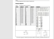
We have the following DI card that can accept 1,2 and 3 wire DI's
( 6DL1131-6BH00-0PH1). We plan on installing this card for use with think top head valve limit switch. From the valve manual it says that connections should be made to pins:
1 and 2 for power supply and
then either pin 4 or 5 for valve indication.

Say for example we are going for pin 5, my question is can this be wired to the card in the following way

a wire from uv0 ( +) on the card to pin 1 on the valve
a wire from DI.0 on the card to pin 5 on the valve
a wire from 0V ( -) to pin 2 on the valve

Am i correct that this is a 3 wire installation and can be connected up as i have described or is there something i am missing.

Thanks
et200sp.jpg thinktop.jpg
 
Yes, you have it correct.
What I found quite confusing is there description of the input module as Sink input (PNP, active high).
The wiring diagram clarifies the intended meaning though
 
Last edited:
Thanks for the reply. Would UV0 and DI.0 not work? Is it not the same as UV5 and DI5?

Thanks again
 
Yes absolutely. I thought you were going for Pin 5 on the input module but you are correct, any of the inputs with their sensor supply will work.
 
Hello,
We have the following DI card that can accept 1,2 and 3 wire DI's
( 6DL1131-6BH00-0PH1). We plan on installing this card for use with think top head valve limit switch. From the valve manual it says that connections should be made to pins:
1 and 2 for power supply and
then either pin 4 or 5 for valve indication.

Say for example we are going for pin 5, my question is can this be wired to the card in the following way

a wire from uv0 ( +) on the card to pin 1 on the valve
a wire from DI.0 on the card to pin 5 on the valve
a wire from 0V ( -) to pin 2 on the valve

Am i correct that this is a 3 wire installation and can be connected up as i have described or is there something i am missing.

Thanks
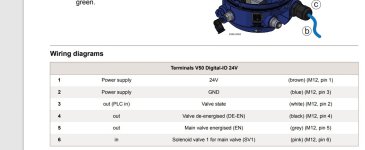
Dont know if its the late night and bad eyes but you could use pin 3 on the valve as well. pin 4 and 5 will give you separate limits and pin3 both. Need to see check the manual when the output in pin3 actually switches
 
Just to add to my original question. I believe the way I have described above will work but I have also been thinking about the following

Would we need to take a Separate 24V and oV from our panel to the think top head and return to the card via pin 4 on the think top? As would we not be powering the thinktops io board, can the card do this?

Thanks
 

Similar Topics

Hello, We have the following siemens DI Card 6DL1131-6BL00-OPH1 ( 32 channel) my question is in relation to the wiring of this card with the V50...
Replies
0
Views
887
Hi, I have a question regarding the DI module 6DL1131-6BL00-0pH1, i am confusing myself with the family of IO, this is a 32 channel module. Can...
Replies
0
Views
990
Hello, We have the following DI card that can accept 1,2 and 3 wire DI's ( 6DL1131-6BH00-0PH1). We plan on installing this card for use with a...
Replies
7
Views
1,487
Hi all, is it safe to remove AI / AO / DI / DO card from ET200x (S) while its powered, I would like to see which OB events occur in such...
Replies
3
Views
2,293
Hi I have a task to change a controlsystem on a plant. The existing PLC is a Siemens IM 151-8 with a profibus mastercard 6ES7-138-4HA00. My plan...
Replies
3
Views
632
Back
Top Bottom