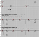
In over my head (ladder logic) Horner PLC, serial Barcode scan

I am going to back off, somewhat, from this statement and recommendation. According the the Horner Automation video, when the RECV instruction's input rung is False, that clears the internal serial buffer.


So when PART_POS1 goes from 0 to one, the RECV will have an empty buffer. That being the case, as long as that happens before the barcode scanner starts sending serial data, and if the scan is a complete 29-character (28+carriage return) read, then the %R01000 buffer should contain a full barcode scan and the RECV will complete and the rest of the logic should be okay.


However, if there is a short or long scan, I am not sure the current code will alwyas trigger the red light. That said, with the [NO Contact PART_POS1], the read and system will be reset for the following part.


i'm baaa'ack... :)


So, I've assembled and wired my second assembly and i'm back to the logic. I've made the changes to the code you last posted.


As of now, i put a part in, barcode scans, goes green, cyl retracts, part leaves Part_pos1 and the light goes off and cylinder extends. Neither of those should happen until Part_pos2 is made.


I've tried a couple changes and still can't seem to wrap my head around what to change to get those in the order i want.


(plus i still think they want to be able to scan the next part, even if the first part has not left Part_pos2 yet)

Screenshot 2021-10-14 143224.jpg
 

Attachments

  • 10142021a.zip
    81.1 KB · Views: 4
Last edited:
Not sure if it helps but on Mitsubishi you have no need to put a not read complete bit in the call to the RX block, if this stays on when next read is done then it will not read the next bar code, I just made it true on my Mitsi & it worked a treat.
 
Stop condition on rung 6, currently [NO %I0001 PART_POS1] should be [NC %I0002 PART_POS2], but that is still going to cause a problem bringing in another part while there is still a part at position 2.


So maybe that needs to be a [NO <rising edge of %I0002 PART_POS2>] so the arrival of the part at position 2 breaks the seal-in on one scan only (Vasily), but leaves the system ready for the next part at position 1 on the next scan while the current part is still at position 2.


I've dug around, i cannot find how to do that. I need to make a one shot for that or ? I can make a coil a -(p)- (positive transition, or rising edge) I don't see a way to make a contact rising edge... maybe just missing something, still a lot of bricks missing in my wall ;)
 
I think you use the contact off the (P) coil so if you have a rung to trigger the P so M10 only comes on for one scan when the logic driving it is true.
Trigger condition
------| |--------------(P) M10

then use M10 in a rung.
M10
-----| |---------.........
 
I think you use the contact off the (P) coil so if you have a rung to trigger the P so M10 only comes on for one scan when the logic driving it is true.
Trigger condition
------| |--------------(P) M10

then use M10 in a rung.
M10
-----| |---------.........

+1

The manual calls -(P)- a "Positive Transition Coil."

It is also straightforward to generate a rising edge with atomic parts:

bit bitM bitRE
--] [--+---]/[-----( )---+---
| |
| bitM |
+---( )-----------+


Where

  • [bit] is the source bit, the rising edge of which is to be detected
  • [bitM] is a memory bit, storing the state of [bit] from the previous scan
  • [bitRE] is the result, and is 1 for the scan, and for that one scan only (Vasily), on which [bit] has a rising edge.
 
Last edited:
+1

The manual calls -(P)- a "Positive Transition Coil."

It is also straightforward to generate a rising edge with atomic parts:

bit bitM bitRE
--] [--+---]/[-----( )---+---
| |
| bitM |
+---( )-----------+


Where

  • [bit] is the source bit, the rising edge of which is to be detected
  • [bitM] is a memory bit, storing the state of [bit] from the previous scan
  • [bitRE] is the result, and is 1 for the scan, and for that one scan only (Vasily), on which [bit] has a rising edge.


Vasily? What is that? I've seen you reference it previously


I'm really sorry i'm being so dumb on this :( You say it's straighforward. I can't even figure out where to add that code... Is it a new rung for the rising edge detection as @Parky showed?
 
Vasily? What is that? I've seen you reference it previously
It's from the movie The Hunt for Red October, see the clip here; yes, I mangled the quote.

I can't even figure out where to add that code... Is it a new rung for the rising edge detection as @Parky showed?

Use what @parky showed., i.e.

  • Current Rung 6, from your last JPEG attacheement uses the Stop/Start pattern; see this link.
  • The Stop condition on current rung 6,
    • currently [NO %I0001 PART_POS1],
    • should be [NC %M000xx PART_POS2_rising_edge],
  • and that rising edge bit should be the output of a Positive Transition Coil (PTC; -(P)-) instruction in a new rung just before current rung 6:
    • [NC %I00002 PART_POS2]=>[PTC %M000xx PART_POS2_rising_edge]
We do not want the Stop condition, which will extend the cylinder and close the gate, to be the part leaving position 1, because that may extend the cylinder before that part moves past the gate. What we want instead, to close the gate, is to detect when a part, which had its valid bar code read by the barcode scanner and parsed by our logic, arrives at position 2: "arrives at" means rising edge detection of bit %I0002 PART_POS2; "is at: would mean NO or NC of same

TL;DR

What I wrote is equivalent to -(P)- and I wrote it for background: that is the logic for how that -(P)- (a.k.a. rising-edge a.k.a. one-shot) works under the hood, so if you are ever working on some ancient PLC that does not have built-in rising-edge detection or one-shot instructions, or maybe you want to do something besides assign 1 to bitRE when the rising edge is detected, then you can build the functional equivalent from scratch.
 
DR is correct, you can also build a one shot falling just have the normally closed contact to drive the pulse.
Many PLC's have pulse functions
OSR = PLS or P, these are one shot rising
OSF = PLF NOTP, these are one shot falling
Some PLC's have built in functions so you do not need to have an output coil as the pulse, examples in Mitsubishi & some others are:
A contact like ----| |----- with an up or down arrow inside the contact denotes using a normal input or bit contact as a one shot.
There are also other functions that have a suffix "P" on them, these do the same job so for example:
MOV or MOVP move data from one variable to another but the one with the suffix "P" only does it once on a rising edge of the logic.
Others are
ADD, ADDP
SUB, SUBP
MUL, MULP
COPY, COPYP
See attached
 
It's from the movie The Hunt for Red October, see the clip here; yes, I mangled the quote.


Use what @parky showed., i.e.

  • Current Rung 6, from your last JPEG attacheement uses the Stop/Start pattern; see this link.
  • The Stop condition on current rung 6,
    • currently [NO %I0001 PART_POS1],
    • should be [NC %M000xx PART_POS2_rising_edge],
  • and that rising edge bit should be the output of a Positive Transition Coil (PTC; -(P)-) instruction in a new rung just before current rung 6:
    • [NC %I00002 PART_POS2]=>[PTC %M000xx PART_POS2_rising_edge]
We do not want the Stop condition, which will extend the cylinder and close the gate, to be the part leaving position 1, because that may extend the cylinder before that part moves past the gate. What we want instead, to close the gate, is to detect when a part, which had its valid bar code read by the barcode scanner and parsed by our logic, arrives at position 2: "arrives at" means rising edge detection of bit %I0002 PART_POS2; "is at: would mean NO or NC of same

TL;DR

What I wrote is equivalent to -(P)- and I wrote it for background: that is the logic for how that -(P)- (a.k.a. rising-edge a.k.a. one-shot) works under the hood, so if you are ever working on some ancient PLC that does not have built-in rising-edge detection or one-shot instructions, or maybe you want to do something besides assign 1 to bitRE when the rising edge is detected, then you can build the functional equivalent from scratch.


Thank you very much. This is helping clarify for me whats happening i think.


As of now, When i scan a part, green light, cylinder retracts, part makes second switch, and nothing happens, Part unmakes part_pos2 and the light goes off and cylinder extends.

That should happen upon making the part_pos2, that way the load operator cannot sneak a new part into the path before the cylinder is raised again.


Just some debugging, i find that if i scan a bad code, Light goes red as it should. If i then scan a good code, the cylinder retracts and both red and green are on simultaneously, Then the red light goes off when part_pos2 makes. Green light goes off and cylinder extends on unmaking part_pos2

Screenshot 2021-10-16 084457.jpg
 
Last edited:
As of now, When i scan a part, green light, cylinder retracts, part makes second switch, and nothing happens, Part unmakes part_pos2 and the light goes off and cylinder extends.

That should happen upon making the part_pos2, that way the load operator cannot sneak a new part into the path before the cylinder is raised again.

My bad: rung 22 should have a -] [- (NO Contact) instruction testing PART_POS2, not a -]/[- (NC Contact) as I wrote.

TL;DR

I'd like to say I put the NC there to give you an opportunity to debug and grow, but the truth is that negative logic is really really useful (see another thread where someone coded a sequencing problem without a single NC contact), and it hurts my brain, and I get it wrong. A lot. Sorry about that Chief ;).

Anyway, if rung 22 used the NC contact, as it should, on PART_POS2, then the rising-edge, 0-to-1 transition of PART_POS2 on one scan puts a 1 in PP2_Edge, for that one scan only (you know who ;)). So the result of the [NC PP2_Edge], i.e. Stop condition of the Start/Stop pattern, on rung 30 will be False, and the output will force a 0 into GRN_LIGHT, i.e. Stop, or turn off if it was on, the green light.

On all other scans PP2_Edge will be 0, so the [NC PP2_Edge] will be True, and allow GRN_LIGHT to be controlled by the other logic on rung 30 i.e. by the Start and Seal-in branches.

As it is, with [NO PART_POS2] feeding the -(P)- PP2_Edge on rung 22, PP2_Edge is assigned a 1 on the one scan scan PART_POS1 has a falling-edge, 1-to-0 transition, which then Stops, via the Start/Stop pattern, GRN_LIGHT, which is what you see.
 
P.S. I am surprised I have not mentioned this yet, but Ron Beaufort put together a series of ~10minute videos that cover pretty much everything you need to know to debug PLC code when it does not do what you want. It takes less than two hours to watch, but if everyone who posted a "why does this not work" ladder logic query on this site read it, those queries would probably drop by an order of magnitude.

See this link; it's basically a form of Rubber Duck Debugging (see here).
 
Last edited:
Just some debugging, i find that if i scan a bad code, Light goes red as it should. If i then scan a good code, the cylinder retracts and both red and green are on simultaneously, Then the red light goes off when part_pos2 makes. Green light goes off and cylinder extends on unmaking part_pos2

Hmm, yeah, more hurt brain malfunction on my part.

I guess the question is what do we want to be the Stop element to be of the Start/Stop pattern for RED_LIGHT? It is currently a part arriving at position 2, so PART_POS2 becomes 1, so the [NC %I0002 PART_POS2] instruction result becomes False on rung 35 and turns off - "Stops" - the light.

If it should rather be the removal of the part from position 1, then change that Stop element to a [NO %I0001 PART_POS1] instruction, so the red light will only transition from off to on when an invalid code is read (one-shot Read_Complete and new_char_is_CR are 1 indicating a code was read on the current scan, and GRN_LIGHT is 0 i.e. indicating the previous rung did not detect a valid code i.e. it did detect an in-valid code).

If it should be the detection of a valid code, then take the [NC GRN_LIGHT] instruction from the Start branch element of the Start/Stop pattern and move it to the Stop element, and remove the [NC %I0002 PART_POS2] instruction. That way, the Red light will remain on until a valid code is read and the green light comes on.

I would go with the former: removing the part from position 1 clears the invalid code "alarm." The problem with the latter is that, if two invalid scan codes arrive in a row, then the red light will be on continuously, so the message to the operator is unclear i.e. did a second scan occur and detect an invalid code, or did a scan not occur and this red light is from the previous part?
 
Last edited:
Hmm, yeah, more hurt brain malfunction on my part.

I guess the question is what do we want to be the Stop element to be of the Start/Stop pattern for RED_LIGHT? It is currently a part arriving at position 2, so PART_POS2 becomes 1, so the [NC %I0002 PART_POS2] instruction result becomes False on rung 35 and turns off - "Stops" - the light.

If it should rather be the removal of the part from position 1, then change that Stop element to a [NO %I0001 PART_POS1] instruction, so the red light will only transition from off to on when an invalid code is read (one-shot Read_Complete and new_char_is_CR are 1 indicating a code was read on the current scan, and GRN_LIGHT is 0 i.e. indicating the previous rung did not detect a valid code i.e. it did detect an in-valid code).

If it should be the detection of a valid code, then take the [NC GRN_LIGHT] instruction from the Start branch element of the Start/Stop pattern and move it to the Stop element, and remove the [NC %I0002 PART_POS2] instruction. That way, the Red light will remain on until a valid code is read and the green light comes on.

I would go with the former: removing the part from position 1 clears the invalid code "alarm." The problem with the latter is that, if two invalide scan codes arrive in a row, then the red light will be on continuously, so the message to the operator is unclear i.e. did a second scan occur and detect an invalid code, or did a scan not occur and this red light is from the previous part?


I reworked and got it into the machine today. Seems to be doing what it's supposed to. I will know for sure on Monday as we will be running production. Easier to see problems then.


Thank you again, I owe you a million dollars. (or maybe a gift card for dinner or something.....)
 
If it ain't broke, don't fix it, but I still do not see how the current logic to read the barcode scanner can be at all robust; if it gets a short or a long code then it may start rejecting valid codes and not recover for some time, if at all.

I suggest the red changes below; at 9600baud it might miss some characters, so running at 2400 or 1200 baud should also be fine.

If that does not work, then I suggest logic based on the method from the Horner YouTube video, i.e. check for stagnation of the [RX Count] value.

If that also does not work, then the changes in orange remove useless cruft and should not affect the behavior of the current logic.

xxx.png
 

Similar Topics

Good Afternoon , I'm sure there are many Ishida Muti-Head Weigh Systems . We have a Ishida CCW-M-214W Multi-Head system . We are...
Replies
1
Views
541
Hi all, have a project which requires reading a weigh head weight over ASCII. Never really touched ascii so struggling a bit. The weigh head is in...
Replies
11
Views
1,245
Good Morning , We have a Ishida Multi-Head Scale . I had experiece with them for chips , crackers , etc. , but now we are using them for...
Replies
7
Views
468
Hello expert I have migrate legacy project that use Applicom OPC DA with 3rd client and S7-400. I see in client code add item string call...
Replies
0
Views
370
Got another one a whole team of us and the OEM cannot figure out. Powerflex525, 20HP VFD, commanded over Ethernet won't turn a motor it's turned...
Replies
32
Views
7,921
Back
Top Bottom