Omron CJ2m Analog logic issue

James Mcquade

Member
Join Date
Oct 2007
Location
Nashville, Tennessee area
Posts
3,683
Hi all,

i have a hot water tank (500 gallon best guess) that uses a valve controlled by the plc to fill it.
there is an analog 4-20 ma sensor that monitors the water level. it is connected to an MAD42 card.
every week or two, we have to drain the tank of water so we can clean it.

i have logic that works as long as the tank is at least 30% full - best guess.
the issue is that when you first turn the tank on, the analog sensor acts strange and stops the valve from turning on.
there is 2 conditions. when the hot water level is less than &2100 turn the valve on , then when it reaches &2100, fill the tank based on a timer until full.

What happens is the Hot_Water analog sensor value goes below 0 and the value turns to (-65535) or goes way above & 3000 and stays for a good while before returning back to normal.

is there some type of filter (plc logic) i can use to fix the issue?
please see the attached picture.

Thanks in advance,
james
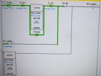
Water level logic.jpg
 
Is your analogue scaled already or are you using the raw input? If your using the raw input your probably should be using signed binary comparators as the analogue inputs usually will read +/-4% full scale and will read into the negatives.
 
The MAD42 card has a configurable resolution of 0 - 4000 or 0 - 8000. It appears from your screen shot and the information you provided, the resolution is set to 8000. It also appears you are using raw values.

Your raw input will read:

-400 at 3.2mA
0 at 4mA
8000 at 20mA
8400 at 20.8mA

This information can be found here in section 2-1-3: https://assets.omron.eu/downloads/manual/en/v4/w345_cs1_cj1_analog_i_o_units_operation_manual_en.pdf As with any Omron manual, break out the Windows calculator and set it to Programmer mode.

To chelton's point, you can see what is happening now. The <(310) instruction is comparing the value as unsigned so if your value goes to -400, it is comparing it as FE70h or 65136 unsigned decimal. If you are actually seeing 65535, your raw value is -1.

As chelton suggests, change your <(310) to <S(312).

In CX Programmer you can monitor the values as signed, unsigned or hex. Keep in mind this is only an interpretation for viewing and not how the values are being treated in the program. Also, if your Hot Water Level symbol is set to unsigned, you'll get a warning when you compile the program. You may ignore this warning or you can change the data type.
 
IO_Rack

"As chelton suggests, change your <(310) to <S(312)."
i'm still learning, what does the "S(312) mean?
Why not use <S(310) ?
regards,
james

James,

The numbers in brackets are the instruction numbers. (310) is an unsigned less than instruction. (312) is a signed less than.

If your coming from AB you will be only used to signed binary integers. With Omron you will need to get used to all the different data types. BCD was used heavily early on, and the scale instructions still output the data in BCD.
 
What happens is the Hot_Water analog sensor value goes below 0 and the value turns to (-65535)


Is anyone else bothered by this? Maybe the minus sign is a typo?

A decimal value of -65535 cannot be represented in 16-bits, and the 32-bit signed integer of that value will be 0xffff_0001 in hexadecimal. Is this some special flag from the 4-20mA A/D conversion process?

I understand and agree the issue is almost certainly some version of interpreting the bits as signed vs. unsigned, but summat doesn't smell right.
 
I noticed that as well but I assumed it was either read wrong or it was a typo.

I can tell from his screen shot that he is monitoring in Unsigned Decimal so his value would have looked like "&65535". Even if the value was 32 bit, the monitoring of the 16 bit register in question would look the same since the upper Word would be ignored. If he were monitoring in Double, it would look like "&65535,D".

I did however double check the conversion value (raw input) configuration. It is as follows:

<Default>0
<Min>-32768
<Max>32767

<Address>CIO2007
<Type>Signed decimal
 
drbitboy,

all production lines are programmed this way.

IO_Rack,
the reading might very well be &65535.

chelton,
"The numbers in brackets are the instruction numbers. (310) is an unsigned less than instruction. (312) is a signed less than."

If i understand you correctly, address (310) is an unsigned value and the S(312) is a signed value.
Why not use the S(310) instead?
I am mostly an AB programmer and am having to refresh my memory on Omron CJ2M plc's. its been 30 years since i programmed Omron.
thank you everyone for your help.
james
 
If i understand you correctly, address (310) is an unsigned value and the S(312) is a signed value.
Why not use the S(310) instead?

That won't be possible, nor is it necessary.

(310) & (312) are not addresses. If fact, you won't need to be concerned about them at all. The instruction itself doesn't require an address like a function block would. If you browse your program (or any Omron program), you'll notice all box style instructions have a number associated with them. This is an Omron internal reference. The refer to them as Function Codes.

If you change the "<" to "<S", the rest will auto-populate. EDIT: It doesn't really auto-populate but just shows up after the instruction is entered.

This is different from AB because in AB, the Data Type (of the Destination, I believe) will dictate how the function is executed. So LES works for everything regardless of Data Type. Everything that will successfully compile, that is.

In Omron, the Instruction will dictate how the function is executed. So you'll need to know and choose appropriately:

<(310) - Less Than, Unsigned
<S(312) - Less Than, Signed
<L(311) - Less Than, Unsigned Double
<SL(313) - Less Than, Signed Double
 
If i understand you correctly, address (310) is an unsigned value and the S(312) is a signed value.
Why not use the S(310) instead?

(310) and (312) are not values, signed or unsigned.

The [<] (less-than) instruction compares two 16-bit integers.

  • (310) tells the [<] instruction to compare the two 16-bit integers as unsigned values
  • (312) tells the [<] instruction to compare the two 16-bit integers as signed values.
  • Neither instruction gives a hoot whether the 16-bit integers were written as signed or unsigned values.
    • So it is incumbent on the programmer to know what the 16 bits of each integer represent, i.e. whether they represent signed or unsigned integers
  • Since in this case the MAD42 card wrote the 16-bit integer value as a signed value ([email protected] to +8000@20mA), and it is possible for the signal to be less than 4mA and the integer value to be less than 0, it makes sense to do the comparison as signed 16-bit integers i.e. to use the <(312) version of the instruction.
TL;DR

Each bit (binary digit) in a 16-bit integer represents a unique power of two:
Bit Signed Unsigned
# Value Value Note
0 1 1 20
1 2 2 21
2 4 4 22
... ... ...
14 16384 16384 214
15 -32768 +32768 ±215

Bit 15 is the key bit here. For example, to get -16384 as the value of 16-bits interpreted as a signed integer, Bits 15 and 14 will be 1, and all other bits will be 0:

  • 16 Bits: 2#1100_0000_0000_0000
  • 1 x -215 + 1 x 214 + 0 x 213 + 0 x 212 + ... + 0 x 20
  • 1 x -32768 + 1 x 16384 + 0 x 8192 + 0 x 4096 + ... + 0 x 1
  • -32768 + 16384 + 0 + 0 + 0 + ... + 0
  • -16384
But note what happens if we let the [<] instruction interpret those same 16 bits as an unsigned integer:

  • 16 Bits: 2#1100_0000_0000_0000
  • 1 x +215 + 1 x 214 + 0 x 213 + 0 x 212 + ... + 0 x 20
  • 1 x +32768 + 1 x 16384 + 0 x 8192 + 0 x 4096 + ... + 0 x 1
  • +32768 + 16384 + 0 + 0 + 0 + ... + 0
  • +49152
So when the MAD42 sees a incoming current signal less than 4mA, say 3.2mA, it writes a negative signed value of -400 to the 16-bits i.e. with a 1 as Bit 15 for a bit value of -32768. But when the [<(310)] instruction looks at those same 16-bits of that integers it interprets Bit 15 as +32768, and compares an unsigned value of +65136 to target (&2100), and since 65136 is not less than 2100, the [<(310)] instruction outputs a False rung state and the valve is not opened.

This ain't rocket science; this is bookkeeping.
 
I kind of misunderstood the misunderstanding.

Nice job on the Two's Complement lesson! It's formatted nicely. I have a hard enough time just trying to strike-through my mistakes.
 
I kind of misunderstood the misunderstanding.

Nice job on the Two's Complement lesson! It's formatted nicely. I have a hard enough time just trying to strike-through my mistakes.


I just said what you had already, but I said it in a pedantic form, to try to make it easier to follow and understand.

The point is a PLC program only deals directly with PLC memory, and that all PLC memory is just a bunch of bits. How you as a user, and how instructions, interpret one bit (discretes i.e. "relay" states) or a group of bits (e.g. 16-bit integers) is entirely context dependent.

In A-B/Logix, we define how a group of bits is interpreted when we declare the tag's "data type" (INT vs. UINT vs. DINT vs. UDINT vs. REAL vs. LREAL etc.).


In Omron, apparently there is no explicit declaration in the data, and the specific instruction chosen (310 vs. 312 etc.) determines the "data type" and the number of bits, and all we pass to the instruction is the address of the first bit of the group of bits. It's basically assembler language.
 
Bottom line: PLCs are not clever; if I tell a PLC instruction to interpret a group of 16 bits at an address as an unsigned integer that is exactly what that PLC instruction is going to do with those 16 bits; it will not try to alert me that another instruction is treating those same 16 bits at that address as an signed integer.
 
I just said what you had already, but I said it in a pedantic form, to try to make it easier to follow and understand.

Thus the single complement! ;) Thank you.

In Omron, apparently there is no explicit declaration in the data, and the specific instruction chosen (310 vs. 312 etc.) determines the "data type" and the number of bits, and all we pass to the instruction is the address of the first bit of the group of bits. It's basically assembler language.

The scary thing with Omron is, you may choose to assign a data type via Symbols. But it doesn't change the way the instructions are executed. You will get a warning if the data type doesn't match the instruction data type.

I say scary but really it's a convenience. I've worked with Omron for so long that when this convenience came along, it didn't do anything for me except cause a little confusion.
 

Similar Topics

Hi all, While i am not new to omron, i'm totally new to the analog part and lost. i have a CJ2M cpu 33. then there are 4 i/o cards card 5 is a...
Replies
26
Views
2,583
Hello everyone, Today i have been tasked with creating a program in cx-programmer to keep a ramp at a certain angle as a tide comes in and out by...
Replies
6
Views
3,252
Has anyone done SMS messaging from an Omron CJ2J-CPU31 PLC? If so could you help please. Omron here in Oz have not had any experience doing this...
Replies
5
Views
123
I have an old plc in the system I have, moxa nport was used to communicate with scada, I want to replace the plc with cj2m cpu33 and eliminate...
Replies
1
Views
63
Hi all, i have 8 CJ2m plc units that show different numbers on the plc display and i am stuck on reading the info. my unit has an ip address of...
Replies
3
Views
98
Back
Top Bottom