OTE instructions not sending signal to corresponding outputs

Memory

Member
Join Date
Aug 2021
Location
NC
Posts
2
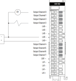
When I force the outputs, some of the LED’s on the card to not correspond to the tag. Pt00 through Pt03 send a signal to the correct outputs.
Pt04, Pt05, and Pt06 send signals to 9, 10, and 11 respectively, on a 5069-OB08 output card.

What would cause this?!?

Program tag Corresponding LED (slot 5)
Local:5:O.Pt00.Data 0
Local:5:O.Pt01.Data 1
Local:5:O.Pt02.Data 2
Local:5:O.Pt03.Data 3
Local:5:O.Pt04.Data 9
Local:5:O.Pt05.Data 10
Local:5:O.Pt06.Data 11
 
Forcing an output with Allen-Bradley systems does not mean you are forcing the output tag. In fact, you are overriding the logic and forcing the PHYSICAL output to energize or de-energize. The output in the logic (and the tag) is unaffected. So, it is entirely common where the output tag will have a zero and show de-energized, but the physical output has turned on. The red "ON" indicator below the instruction is your indication that the field device is being forced on.

Forcing an output is like placing a jumper wire with 24V on the output point. The output will respond, but the logic has no idea you have done that.

OG
 
Last edited:
Right, but it's the physical output that isn't responding.
When I force Pt01, physical output one turns on.

But when I force Pt04, physical output nine turns on.
When I force Pt05, physical output ten turns on.
When I force Pt06, physical output eleven turns on.

I started running the forces because the output devices (in this case valves) were not being actuated with the program logic was showing the OTE's were going true.

Pt01 through Pt06 go to the same types of valves.
Pt 01-Pt03 send a signal to their correct corresponding outputs.

Pt04-Pt06 are sending a signal to the incorrect PHYSICAL output.

I am at total loss.
 
Yeah, and I didn't word my response very well. I went back and edited it.

That got me too. It was like wait, it is only an 8-pt card, how would it have indicators above 7? Didn't make sense until I saw the diagram.

OG
 
Pt4(output 4) is pin(terminal) 9.
Check your coil wire to make sure it is not connected to pin(terminal) 4. That is the common for the first 4 outputs
 
For this reason I HATE Rockwell/AB cards... Lets start the IO in logic at 0.. on the terminal strip at 1.. count commons as part of the normal terminal number... etc. a 16 point card ends up with 39 terminals... what a pain in the *** to explain to techs remotely. I've started writing the terminal numbers into the IO sheets I generate for facility MCCs.
 
S5, S7, B&R, Baumuller. I have it like that on them all. I agree. I like to see DO5.4 pin 9. A new piece of hardware can drive me crazy. I believe it is a manufacturing point because the same case is used for 8 pt, 16 pt, isolated outputs, and on and on.
 

Similar Topics

Can I use multiple OTE instrutions for the same tag at various different routines inside the program? I know that doing this would cause issues in...
Replies
8
Views
7,680
Something I've never thought about before... maybe you folks have some thoughts or experience. I have a customer that uses a Weidmuller, Modbus...
Replies
2
Views
114
Hi, We have been facing a issue with SCADAPack 474. Configuration is like below. RTU 474 + 6103 PS + 5606 IO Mix Module + 5414 DI Module Only...
Replies
0
Views
73
Hello, Can anyone recommend an expandible IO module with OPC UA? I've deployed the Emerson RSTIO-OM module and it works great, but it has a...
Replies
0
Views
56
So I'm pretty new around here but I come looking for advice or suggestions to research. Im the plant electrician/SCADA guy for a warer department...
Replies
8
Views
294
Back
Top Bottom