RS232 Splitting Headaches

In general, a single data byte in RS-232 consists of:

Start Bit
Data Bits
Parity Bit
Stop Bits

The settings that apparently work between the PC and MGI are one Start bit, Seven Data bits, one Odd Parity bit, and two Stop bits. "7/O/2" adds up to an 11-bit frame.

The settings that apparently makes data visible in Tera Term is one Start bit, Seven Data bits, no Parity bit, and two Stop bits. "7/N/2" adds up to a 10-bit frame.

But from what I'm reading, the 5069-SERIAL gives framing errors when set for 7/N/2 and connected to the "sniffer" wiring.

There could be two sources for those framing errors: an incorrect Parity bit, or fewer than two Stop bits. The module has a specific parity error indication in the status tags, "Ix.ASCII.ParityError", and another for different framing errors, "Ix.ASCII.FramingError".

Some devices just don't support 11-bit serial framing. The most common serial framing is "8/N/1", which is 10-bit.

But most devices do. A typical FTDI serial/USB chipset can use either one. The 5069-SERIAL user manual says that it supports both. Some virtual serial ports don't support parity bits.

I personally prefer RealTerm to TeraTerm. Despite its kludgy interface it works well at a very low level with the handshaking and framing.

If this were my system, I probably would have broken out the CleverScope, which can be set to decode RS-232 frames inline. Pretty cool.

At least make sure when you change the framing settings on the 5069-SERIAL that you give it a full reset, maybe even a reboot. It *should* handle framing changes with grace, but you never know.
 
Last edited:
Apologies for the late reply.

It is a DB9 connection for those asking, but the pinout MGI side is not standard. On the PLC/Laptop Side, the pinout is standard, but we drop the Tx line to stop the hang-up.

For those who asked, with the configuration 9600,7,N,2 on both devices, we are able to successfully read in the correct characters sent directly from Tera Term to the PLC. This complicated things even further.

After a bunch of iterations here is what we have found.

All configs were at 9600 baud, but with different configs of Data, Parity, and stop bits.

At 7N2, we got bad data, but consistently bad data. The same message but the characters were wrong. Indicates a framing error.

At 7O2, we also got consistently bad data, but different bad data, which it still seems are having a framing error.

At 8N1, we appear to get partially correct data. It seems that when an ASCII character naturally would end with a 0, this would be sent to the PLC correctly, and otherwise would give us junk data. The correct message should be an 11 byte message consisting of "+14.4221I(cr)(lf)". I have attached an image of tag monitor looking at a message. the 1, 4, 2, and I are correct. The $8A should be a '+' and the $AE should be a '.', and so on.

uTBIXdj


We have a few theories.

I noticed on the second laptop terminal software we used that the Data was coming in specifically as an unsigned character. The 5069-Serial Card puts the bits into a Signed short integer. Could this unsigned to signed casting be the source for the framing error?

My coworker with much more experience than myself suggests writing a little subroutine that purposefully drops out the parity bit of each byte to force no parity. The theory is that the 486 and the Laptop are capable of interpreting that Parity bit in a looser way, whereas the 5069-Serial card needs stricter requirements and does less fixing for us.

We are offsite for a little bit, but I really want a strategy I know will work before we go back. Lots of other testing for this system, but this single issue is getting way too in the way.

I still appreciate all the assistance. I believe we will figure it out eventually!
 
Attachment is missing.

8N1:0x8A would be 7N2:0x0A (linefeed, perhaps the character before the '+') with a 1 in the high 8-bit data bit i.e. the first of two stop bits.

8N1:0xAE would be 7N2:0x2E i.e. '.' as you note, again with a 1 in the high 8-bit data bit i.e. the first of two stop bits.

If that is the case, you might be able to mask each character's received 8-bit ASCII code with 127 (0x7f) to recover the 7-bit value.

Still, why doesn't 7N2 work?

Have you tried 7E1 and 7O1?
 
I am close to wits end and would appreciate any new perspective.
This is my perspective:

If you go this way of breaking into such an ancient system to "sniff" the data, you end up with an awful cludge that is difficult to maintain, and will have to be overhauled again in some years.
I would go another way. I would overhaul the data acquisition part completely and I would remove the 486 PC and all the serial stuff. In place of the obsolete parts I would use only current parts and implementing current methods.
 
At heart I am a diagnostician, not a designer, so this sort of thing fascinates me. This is definitely at the point I would be getting out an oscilloscope with serial protocol decode functions. Even the cheapest PicoScopes include that feature.

SandwichMagic's description of the "partially good" data with 8/N/1 framing as compared to 7/N/2 and 7/O/2 is fascinating.

I'll be that if you got down to the circuit and chip level in the Multi-Gauge Interace device you might find a microcontroller that is bit-banging the serial interface with a timed interrupt, instead of using an onboard UART. Or you might find an old oscillator that has degraded and isn't handling crisp 104 microsecond serial pulses well. The fact that the MGI even has a non-standard RS-232 pinout also suggests that its circuitry and implementation aren't exactly EIA Recommended Standard specification compliant.

>At 8N1, we appear to get partially correct data. It seems that when an ASCII character naturally would end with a 0, this would be sent to the PLC correctly, and otherwise would give us junk data

Let's chew on that a little, with drbitboy's input that the "wrong" value in place of the ASCII "+" and "." is different only by the Most Significant Bit.

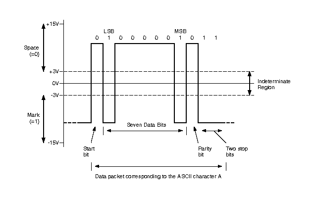
RS-232 data signals are always negative voltage = data 1 = "Mark" when the line is idle. The Start bit is a transition from negative to positive voltage (1 to 0), and the STOP bits are positive voltage (0).

This graphic shows it well (link):

RS232_signals.gif
 
I am with Ken: get out the scope! I have seen scope apps for phones using the analog audio jack up to 20kHz or so, which is on the edge here but might work.

SandwichMagic said:
we are able to successfully read in the correct characters sent directly from Tera Term to the PLC

Does this mean that if the 486PC was no longer required, the PLC could replace it?


Is the PLC able to also receive data from the 486 i.e. the polling message?


Another suggestion: instead of splitting the signal, perhaps the PLC could have two serial cards and be in the middle of the MGI and the 486 doing passthrough, i.e. listening in both directions and passing the data through while looking at it i.e. while doing the splitting in software. It be even simpler to do this with a Linux box e.g. a RaspberryPI; it could be prototyped very quickly using e.g. a laptop with a couple of USB/RS-232 dongles; I would be surprised if the code were not already on Github. If FTV had to be the final step, the data could be passed to the PLC via some ethernet-based tool e.g. pylogix, in Rube-Goldberg/Heath-Robinson fashion.


Update: passthrough possibly here?


Or here?
 
Last edited:
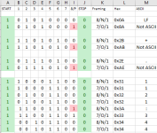
The Odds Get Even

A device set for "Odd parity" sets a bit when the number of "1" data bits is even.

A device set for "Even parity" sets a bit when the number of "1" data bits is odd.

It might be useful to compare the bit patterns for various values with 10-bit frames configured for 8/N/1 and 7/O/1.

When you're "set for 8/N/1" and are reading the "partially correct" data that you describe, you're probably ACTUALLY decoding data as "7/O/1".

Sometimes parity and framing problems are resolved by "try all the variations until one works". Sometimes they really do require getting down to the highs and lows and ones and ohs.

Odd_Parity.png
 
Last edited:
@SandwichMagic: could you post a message string and what the PLC sees with 8N1 when the message is something like "+14.4221I(cr)(lf)" or similar? I don't care what form, although hex would be best and decimal next best.
 
Figured I should post back here once before I start a new thread. With the config of 8N1, I ran the junk data through a mask that set the first bit to 0 and it worked! Messages come in just fine after the translation and are totally usable. I still think there is credence to my theory of signed vs unsigned, which makes sense to me why stripping out the first bit works.

Sorry for not updating and resurrecting this dead thread, but figured that I should at least give some closure before I beg for help yet again.
 
nice, that's a sweet hack!

thanks for the follow-up.

just curious: was the mask 127 (0x7F) or 32767 (0x7FFF) or summat else?
 

Similar Topics

i have an device which can support serial (RS485,RS232),CAN protocol . i want to connect it to an existing MIB 1553B bus ,what device will I need...
Replies
0
Views
99
Hello: I have to connect a RS232 Modbus RTU slave that only has Tx, Rx and GND signals to a Modbus RTU master. However, all RS232 to RS485...
Replies
3
Views
237
Hi to everybody. I need to read the first 12 characters of the message that a barcode reader sends to the ascii card (1734-rs232 ascii) and I...
Replies
8
Views
729
I have wasted a week trying to figure out how to connect an SLC5/03 with my laptop. I do not have and can not Buy the 1747 UIC and PC3 cables. I...
Replies
14
Views
2,558
I'm trying to manually convert a Beijer E200 HMI project onto to a new Mitsubishi GOT gs2107-wtbd. The PLC is a very old A-series AS1CPU and is...
Replies
1
Views
384
Back
Top Bottom