RSLogix 5000 Instruction Type Needed

KoalaWala

Member
Join Date
Jan 2021
Location
Minneapolis, MN
Posts
11
Hey guys, thanks for taking the time to look into my question. I'm building a system to monitor several other systems for faults and one of the things I want to monitor is our incoming electrical power as we have a lot of issues with it.

If there's a fault in the system, it will send everyone who needs to know, a text message. I was thinking it would really be nice if I could have the messages be a little more specific than just "Electrical Failure from Service 1"

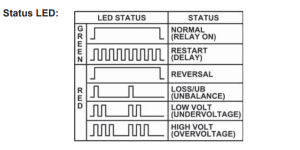
I found a device that monitors several different kinds of issues and returns the specific problem in the form of a blinking LED light. (see attached picture) Is there a way to capture those various pulses from the LED to an input, and have the PLC trigger a different output for each issue?
Capture.PNG
 
Is the frequency of the flashing messages always the same, regardless of the message or color of the light?

I assume the parser would use two inputs: one for red; one for green. If one input (color) is on or flashing, the other is off. Is that correct?

For normal (Green) and reversal (Red), are lights on solid, or do they stay on like the image (a long time on, the briefly off, then back on again)?

I think a debounce-style pattern/circuit that counts edges should do the job.


It's quite the Rube Goldberg/Heath Robinson, but it is doable. I suspect you will spend more time fiddling with getting the text message working.
 
Last edited:
Is the frequency of the flashing messages always the same, regardless of the message or color of the light?

I assume the parser would use two inputs: one for red; one for green. If one input (color) is on or flashing, the other is off. Is that correct?

For normal (Green) and reversal (Red), are lights on solid, or do they stay on like the image (a long time on, the briefly off, then back on again)?

I think a debounce-style pattern/circuit that counts edges should do the job.


It's quite the Rube Goldberg/Heath Robinson, but it is doable. I suspect you will spend more time fiddling with getting the text message working.


I don't really care about the green light function. The mechanism has a relay that is triggered when a fault is detected. Then, one must go to the mechanism to find out the exact issue. The reversal is red and stays red. Again, that's easy to replicate, no issue. But something that counts the blinks within a given time...I don't know how to set that up because it's continuously blinking but with pauses in between.

The texting part is no issue. That's fully setup, tested, and working great.
 
Here is a parser for the green light (which I now see you don't need, LOL).

I'll have summat for the red shortly.
 
P.S. this is in RSLogix 500 (Micro Starter Light, actually), but most of it should translate pretty easily.

The emulation in the input buffer routine will not work as there is no direct analog the free-running clock in register S:4, but the emulation is only for testing without actual hardware.
 
But something that counts the blinks within a given time...I don't know how to set that up because it's continuously blinking but with pauses in between.

What is the character of the red light when it blinks (e.g. period and duty cycle)?

Also the meta-cycle i.e. how long between the first blink of any sequential set of one, two, or three blinks?
 
Last edited:
What is the character of the red light when it blinks (e.g. period and duty cycle)?

Also the meta-cycle i.e. how long between the first blink of any sequential set of one, two, or three blinks?

Blinks are per second, with a one second pause. So the cycle is 2 seconds regardless of which fault is at play.

If something is faulted, (ie, three blinks) and another fault occurs (two blinks) the original fault must be cleared manually before a new fault condition can occur.
 
This is how I am interpreting that:

So a 1-blink fault is two seconds (500ms on, 500ms off, 1000ms off)?

And a 2-blink fault is three seconds (500ms on, 500ms off, 500ms on, 500ms off, 1000ms off)?

And a 3-blink fault is four seconds?

1 blink is correct, 500ms on, 500ms off, 1000ms off
2 blinks 250ms on 250ms off 250ms on 250 off 1000ms off
3 blinks 166ms on 166ms off 166ms on 166ms off 166ms on 166ms off 1000ms off
 
Let me try again.


- any fault uses 2s for a single meta cycle of 1, 2, or 3 blinks.

- in the first second, there the red comes on (and goes off) 1, 2, or 3 times
- in the second second, the red light stays off.


Is that better?
 
1 blink is correct, 500ms on, 500ms off, 1000ms off
2 blinks 250ms on 250ms off 250ms on 250 off 1000ms off
3 blinks 166ms on 166ms off 166ms on 166ms off 166ms on 166ms off 1000ms off


ah, got it.


So if red stays off for between to 501ms and 1500ms, the blinking part of that fault's meta-cycle is done.
 
Here you go; I did some brief testing and the results seem reasonable.


Let me know if you have any trouble porting to RSLogix 5k. It does not need the emulate bits or the incrementing float in the input map subroutine; that will save me writing those comments; I only used the emulate bits for testing. That said, having an the input map/buffer is a good idea since Logix may have asynchronous I/O.

The ordering of the strings are jumbled, and there is no reason to interleave the green-related strings with the red related strings; they should be re-arranged when converting to tag-based addressing e.g. the FIFO could be its own array of strings. For that matter, it could use numbers instead of strings if some downstream process can handle the text better; I would assume the PLC is not handling the text messaging details itself.

It might make sense to do some more consistency checks; e.g. both lights should not be off.

I changed the red TOF timer .PRE value to 650ms, instead of 750ms, to detect the end of a series of blinks; that was necessary to make it work in my environment emulating red and green light data from the MicroLogix 1100 free-running clock, which forced me into a 1648.4ms cycle instead of a 2s cycle.
 
P.S. this is just a quick pass; it could probably be a good bit cleaner, but I was only going for functional and did not go too deeply into edge cases.
 

Similar Topics

I"m trying to average an array of DINT's called FIFO_ARRAY. It has 1000 elements in it. Here is what I have entered into the AVE instruction...
Replies
11
Views
4,731
Hello Please Help, I want to use a FSC instruction that will scan 20 DINT arrays. If the arrays are greater than 1000 display the value. How do I...
Replies
4
Views
1,769
Hi There, When i did FRD instruction in SLC 500 its working, when i try to simulate in RSLogix 5000 same way as i did in SLC 500 which is not...
Replies
14
Views
2,729
This is a real simple interface problem. Typically when I'm developing in ladder I will Ctrl+C an instruction and Ctrl+V, the new instruction will...
Replies
2
Views
1,678
Hi there, I am trying to create an Add=On Instruction to help me manage some alarm conditions in my application. My AOI has one Boolean output...
Replies
7
Views
2,626
Back
Top Bottom