You are using an out of date browser. It may not display this or other websites correctly.
You should upgrade or use an alternative browser.
You should upgrade or use an alternative browser.
Siemens TIA Portal V15 4 way intersection with Traffic Lights
- Thread starter romanstuder
- Start date
JRW
Member
Use S7 Graph
That will impress your instructor
actually you didnt say the plc type......
That will impress your instructor
actually you didnt say the plc type......
drbitboy
Lifetime Supporting Member
#1 what @JesperMP wrote. Nobody wants to visite a plant where the person who programmed the PLCs in that plant did not learn and understand PLCs on their own, because that plant will not be safe.
Is the course EEM 252 at Trident College?
Why is it urgent?
What has been covered in the course so far?
What other programming experience do you have?
Do you have access to a PLC, or at least the IDE*, at home, or only while in a lab?
Are you supposed to write this program in a PLC IDE*, or on paper? How will you test your program?
* Integrated Development Environment, i.e. TIA Portal
Do you understand the PLC scan cycle and what it does? If not, watch this video series.
Almost everything else you need is probably available at this link.
Ken Moore
Lifetime Supporting Member
I would assume all adults, even if they don't drive have encountered traffic lights.
So...you know the process.
If you cannot at least make an attempt to program the requirements, then perhaps you should explore other opportunities.
So...you know the process.
If you cannot at least make an attempt to program the requirements, then perhaps you should explore other opportunities.
drbitboy
Lifetime Supporting Member
Each crosswalk will have its [Cross] light on steady or flashing for 40s, and I suspect it is important that the corresponding traffic light be green (or perhaps not red?) for that entire 40s.
"Crosswalks will not override traffic cycles."
"Crosswalks will not override traffic cycles."
- What happens if someone presses the [Cross actv] button when there is less than 40s of green left in the current cycle?
- Does the crosswalk period extend the green time, or would that be an "override" of the traffic cycle, so the crosswalk waits until the next green cycle?
- Does an active 40s crosswalk period prevent the 15s car sensor override?
drbitboy
Lifetime Supporting Member
... I understand how to get the traffic lights to work, but the cross walks and car sensors throw me off.
Can you show us how you get the traffic lights to work (e.g. post a screenshot of the logic), and we can go from there?
The way to solve this kind of problem is to break it into separate pieces, or states of the system at any given time. How a PLC program controls a system on each scan cycle is determined by two thing, and two things only:
- the state of the system i.e. how the PLC program left the system at the end of the previous scan cycle, and
- the state of the system inputs on the current scan cycle.
- reads the inputs, and considers the state of the system (as noted above),
- determines if the combination of the state of the system from the previous scan cycle coupled with the new states of inputs on the current scan cycle should cause a change the state of the system, and
- and finally write that new state; writing the new may involve
- EITHER external outputs, such as the various lights,
- OR state information stored in the bits of the PLC memory, such as booleans and timers
So the first thing you need to determine, once you have identified all of the inputs and outputs, is how many states there are in this assignments' system, and what those states are. Can you identify all the states of the system? Ignore the crosswalk for now, because the crosswalk does not override the main traffic lights.
Defining the states, determining which state the system is in, determining which transitions are allowed*, and identifying the events that cause transitions between states is about 90% of the problem.
The other 10% is what to do in each state. For example, whenever the system gets into the state "yellow 1/3 light is on," then I hope it is obvious that the PLC will run a timer, and the expiry of that yellow 1/3 timer is the trigger for the transition out of state "yellow 1/3 light is on."
You see, the best way to solve this kind of problem is to apply a software principle called "separation of concerns." In this traffic light problem, there are two concerns
- managing the state of system and the transitions between states,
- managing the output image* and internal state entities (e.g. timers) depending on the current state of the system.
The PLC program comprises instructions. In the simplest concept of a PLC program, each PLC Instruction does either, or both, of two things: examine the state of one or more memory bits' states before the instruction is evaluated; manipulate memory bits based on that examination. Also, in Ladder Logic, there is also the state of the input and output rungs of each instruction; these can be though of as transient memory bits that are created, written, and evaluated on the fly as the PLC program scan evaluates each instruction on each rung.
The point I am getting at is that, to write this program, you need to narrow your focus to how you will model the traffic light system in PLC memory. Because the PLC program you write will only interact with the memory bits of the PLC model you design, and it is unlikely that you will be connecting the PLC's output or input channels to physical lights and sensors.
* Note that the PLC program does not manipulate the physical output channels or examine the physical input channels. The only data the PLC program can manipulate or examine are bits in PLC memory. The physical input channels are examined by the PLC I/O scan and the results are written to an "image" in PLC of those channels states. Likewise, the PLC I/O scan examines the output "image" in PLC memory, written by the PLC program, and writes the values from that image to the physical output channels.
drbitboy
Lifetime Supporting Member
That was a bit a long speech, but the point of it is this: the reason the "crosswalks and car sensor throw [you] off" is most likely that you do not have a clear model of the entire system, neither in your head nor in the PLC memory.
JRW
Member
One way of doing it is to use a step sequence with interupts (not hardware but triggeres to interupt the sequence i.e. skip over or use these for the crossing sequence, this could be done with sequence bits but become messy so perhaps use an integer value for that particular sequence then step on.
The best way is to use steps of say 10 that way if you need to add more steps inbetween it is easy.
Try creating some sort of flow chart & use that to give you an idea of the steps for example:
Step 0 IDLE (Not strictly needed but good for initial testing.
Step 10 N/S green, E/W red
Step 20 Crossing N/S initiated by button
Step 30 N/S goes amber
Step 40 N/S goes Red
Step 50 Crossing green
Step 60 Crossing flashing green
Step 70 Crossing Red
Step 80 E/W goes Red/Amber
Step 90 E/W goes Red
& so on
Go b ack to Step 10
There will be more steps & the timers required, you can add things like shortening the sequences if for example the pedestrian buttons are pressed or even traffic flow over sensors etc.
Without say the pedestrian button pressed then skip the pedestrian sequence by jumping past step 20 & 50, 60 the above is not the complete sequences as this is up to you to produce the complete sequences required for all the functions. i.e. time delays steps in the sequence etc.
The way to use the sequence integer is in the different traffic lights outputs use a compare for the seq. steps to turn on the correct traffic light outputs.
Example:
Seq = 10 N & S Light Green ouput
by using AND/OR of these sequence values it will energise the correct outputs at the correct times.
Here is a starter just use this for reference you need to create your own code this is just a simple E/W & N/S traffic lights as in IUK no crossing interuption etc.
Attachments
Puddle
Member
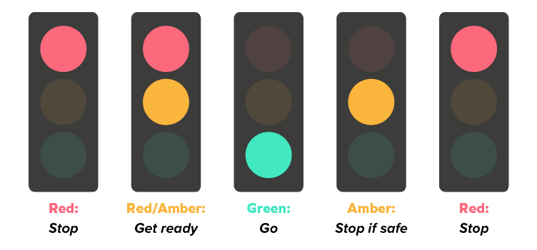
First, figure out the sequence. Is it a 5 step sequence as below?

Start from step 1, figure out what you need for the next step. Work from there and test it until it works. Your first program will not be right the first time.
Something that may help for the 0.5s crossing light flash, go to Device Configuration on your PLC, properties tab, System and Clock Memory, then tick the box marked "Enable the use of clock memory byte" then by default bit M0.3 will become a 2Hz cycle. This will save you a timer and possibly merit extra marks.
drbitboy
Lifetime Supporting Member
OP is from South Carolina, USA, probably attending one of the SC state-created technical colleges (Trident, Orangeburg-Calhoun, etc.), so simultaneous red/amber is not a thing. What is that for, anyway? A drag strip? Or to ensure you hit the car running the light the other way?
I am only guessing, but I think they were looking to be provided the answer, and "urgent" means they waited until just before the assignment was due.
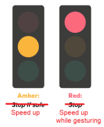
Btw, I need to correct the labels on the last two:
I am only guessing, but I think they were looking to be provided the answer, and "urgent" means they waited until just before the assignment was due.
Btw, I need to correct the labels on the last two:
Rsflipflop256
Lifetime Supporting Member
Help the boy learn but dont do his homework for him!!!!! Thats how you end up with bad controls engineers
Ken Moore
Lifetime Supporting Member
There is a stop light just like this about 2 miles from my house. A county road intersects a state hwy. The county road has limited traffic, so it only cycles to the county road when cars are present. The big difference is the cycle time, the state hwy gets 4 minutes, and the county road, 2 minutes. What gets my shorts all bunched up, is the county road folks, sit there on their cell phones, not paying attention, the light changes to green, and they don't move for 30-50 seconds, (This is why cars have horns!), then they go. So...instead of 4-5 cars getting to go, only 2. Of course I use the county side, and it's usually backed up, when I have an early morning errand.
Puddle
Member
OP is from South Carolina, USA, probably attending one of the SC state-created technical colleges (Trident, Orangeburg-Calhoun, etc.), so simultaneous red/amber is not a thing. What is that for, anyway? A drag strip? Or to ensure you hit the car running the light the other way?
Standard UK traffic light sequence. Most people don't notice, but obviously everybody on here is very familiar with traffic light sequences! Red/amber is there to show that it's changing to green, so you know if you see a single amber then it's about to go red.
Similar Topics
Hello,
If the date on the license manager of tia Portal has expired, can I still work with it? or is this just to keep the program up to date...
- Replies
- 7
- Views
- 218
Hi everyone
I've created an FC that includes the blocks TCON, TDISCON, TSEND and TRCV.
This block has to be as generic as possible across...
- Replies
- 15
- Views
- 1,536
Hello, i can find the CPU when searching for it. But when I go Online i just get the icon for "Not compatible" everywhere. I get no additional...
- Replies
- 4
- Views
- 1,204
Hi, I want to initialise some tags on first scan only. As they are related to wall-clock time, I want to do the initialisation when the PLC first...
- Replies
- 4
- Views
- 1,187
good , how do i calculate the instantaneous flow according to the flow totalizer in the tia portal ?
1 pulse = 1m3/h
- Replies
- 18
- Views
- 1,578


