Hi, I'm quite new to Rockwell PLC and currently trying to implement the following
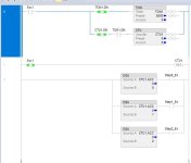
if Sw1 then
for i:=1 to 20 by 1 do
xEnable := 1;
bit := bit + 1;
if delay.DN then
xEnable := 0;
end_if;
end_for;
end_if;
delay.TimerEnable := xEnable;
delay.PRE := 5000;
tonr(delay);
So once the Switch is on the variable bit should be incremented gradually with each step having 5 second delay, but running the code makes the bit increment straight up by 20 without any noticeable delays. Could someone please explain how does Studio 5000 implement the programs and how should I reorganize the code to achieve what I want?
Background
PLC programming is primarily about
time, and the scan cycle is the clock;
when something happens is more important than
what happens.
If you don't know what the scan cycle is,
watch this video series.
General
The code above, and the fact that you are new, suggests you need to understand the scan cycle a bit better. It is very different from "conventional" programming; do you have any other programming experience? Is this an assigment for a course?
Specific
As noted by others, the code above, does not make sense in a PLC: the FOR loop simply counts to 20 on
every scan cycle (when the value of Sw1 is 1), so that happens once every millisecond or so, and the eventually timer expires after 5s, and is disabled on the next scan cycle (again, when Sw1 value is 1).
Just as an example, the TONR instruction on the last line is evaluated (executed) once per scan cycle, and that is the
only time when the
delay.DN bit's value can change from 0 to 1. So the
IF delay.DN THEN ... logic does not need to be inside the loop (even if the loop was necessary) because
delay.DN cannot change in the loop.
Also, there is no code in your example to reset the TONR, so the timer will run to expiry after 5s (5000ms), whether or not the value of Sw1 is 1, and then
never run again. because the value .DN will be 1, which will make the value of xEnable 0, which wil; disable the timer
but leave the value .DN at 1. I think you may have meant to use TON, where the timer resets when its
IN parameter (somewhat,
but not exactly, analogous, to the
.TimerEnable attribute of the TONR structure). That is, unless you want the TONR to only accumulate time when the
Sw1 value is 1.
See the behavior of the TONR instruction
here*; see the behavior of the TON instruction
here*. There is also an interesting article about the TONR instruction
here.
* N.B. none of those are
@OkiePC-safe links.
But again, none of this will make sense until the scan cycle and its implications are fully understood. If this is part of a class and the syllabus has not yet covered the scan cycle, then the syllabus should be corrected to do so. One implication is that the .DN bit of the "delay" structure cannot change until and unless the TONR instruction is evaluated**; another is that loops within scan cycles are rarely necessary, especially if they depend on inputs***, and the TONR is effectively an input here, to change; it is better to use the scan cycle as a
de facto loop.
I suggest you watch the video series mentioned above, and watch it repeatedly until you can cite the narration before
@Ron Beaufort says it.
** that is not true in all PLC brands, but it is true in Logix.
*** that is not necessarily true in Logix, but it is true for most other PLC brands, including non-Logix Allen-Bradley PLCs.