Using BTW/BTR in PLC5 to read from 32bit flex IO

Salman S.

Member
Join Date
Oct 2016
Location
Malaysia
Posts
41
I want to use PLC5 to communicate with flex IO, using RIO. Before I proceed I want to clarify my confusion about the addressing scheme, as I am not acquainted whatsoever to it. I have read the reply by RON in the thread below but I just wanted to see if I'm on the right page.

http://www.plctalk.net/qanda/showthread.php?t=76624

Lets say the flex chassis contains 8 1794-IB32.

Given that there are 8 32bit modules, which of the two is correct?

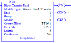
1. 8 BTR instructions addressed to a single rack, groups 0-7.
2. 4 BTR instructions addressed to rack 1, groups 0,2,4 and 6. 4 BTR instructions addressed to rack 2, groups 0,2,4 and 6.

Furthermore should the BTR length be 2 (32bits)?
Also is the group parameter in generic block transfer referring to the starting group? So for a scenario like the one attached I'd be reading from group 1-5?
Lastly, given that a rack contains 8 groups, what happens if the length exceeds 8, will it read to the next logical rack?

Any help will be greatly appreciated đź“š
plc forum picture.PNG
 
Before attempting to address any additional I/O you will first need to acquire (and provide us with!) the entire image of the system.

What type of PLC5 are you working with?

How many available Logical Racks are already being used? Are the unused Logical Racks enabled at the CPU level?

How are you going to address the new I/O (1/2 Slot Addressing, 1 Slot Addressing, 2 Slot Addressing)? The 1794-ASB RIO adapter your modules will be connected to will need to be setup accordingly.
 
Thanks for the response everyone.

So what I gather from the above comments is digital IOs essentially gets mapped to the IO images in the PLC5, based on their rack/group/slot.

Before attempting to address any additional I/O you will first need to acquire (and provide us with!) the entire image of the system.

The reason I didn't provide much details about the system as I was inquiring more on the addressing scheme than assistance for a particular system, as I hope to manage based on the advise.

Just for future reference, say I was using an analog IO like the 1794-IE8, could anyone enlighten me on the following questions,

Is the group parameter in generic block transfer referring to the starting group?
Is group still considered 16bits in the context of BTW/BTR?
 
As Mike_RH says - read the manual chapter 3 - page 3-6 shows you a standard layout and group addressing - not the starting group for the entire rack, but where you actually place your IE8 module within that rack.

Page 3-7 shows you the 32-point addressing....
 
Is the group parameter in generic block transfer referring to the starting group?

Yes.

Is group still considered 16bits in the context of BTW/BTR?

A PLC5 I/O Group is an addressing unit that corresponds to an Input image-table word (16 bits) AND an Output image-table word (16 bits); 32 bits in total, 16 Inputs and 16 Outputs.

As stated numerous times above:
You don't need any BTR/BTW programmed data transfer for Digital Type I/O on RIO networks.;only Analog Type modules will need it.

What you do need to know though is where in the PLC5 memory is the new data going to be mapped to!.

PLC5 memory (I/O Logical Racks containing I/O Groups) is setup at CPU level; if one attempts to add I/O and read/write it within a Logical Rack and Group which is already being used by the application, one could bring the entire place to a screeching stop if not worse.
 
As stated numerous times above:
You don't need any BTR/BTW programmed data transfer for Digital Type I/O on RIO networks.;only Analog Type modules will need it.

That point is well and clear, no worries. I was inquiring for analog modules, for future reference.

Anyways I sort of got the picture now, enough to get me started.
Thanks dmargineau for your help.
 

Similar Topics

I am new to RIO addressing. The system that I am working on has a SLC 5/05 reading data from a 1746-NI8 (8 input analog card) that is located in a...
Replies
16
Views
4,851
Hi, I am having great problems trying to read data from my DVT legend 540 camera. The PLC is an Allen Bradley SLC 5/04 that will control...
Replies
5
Views
2,195
I need the secret for creating a BTW/BTR using SLC 5/04. The M0/M1 files discussed in the instuction help are confusing, how to install or...
Replies
4
Views
2,492
I have a project to automate four generator sets. The system will monitor and store the load demand of the factory. Once there's Power outage, the...
Replies
0
Views
64
Adding ethernet equipment to an existing panel that has none. We have some solid ethernet cables coming from other remote cabinets that I plan to...
Replies
3
Views
124
Back
Top Bottom