I thought the encoder pulse rate (and thus the shift rate) for the different speeds would make up and cover the speed change
[Update: of course my long-winded explanation is much later than others, so read those first as you might grok the problem quicker]
General statement: essentially all computer programs, and certainly all useful PLC programs,
model some real-world process; the
primary design choices for a computer
model are the levels of fidelity between the model and the real-world processes that are modeled. We care about the pass-fail status of a label, and that is a binary state so it is easy to model with high fidelity; we don't care about the color of the operator's socks, so we don't model it at all.
Read carefully what
@Steve Bailey and
@parky have written.
When the bottle label is detected by the camera, it is at an inotial fixed position, let's call it
P0. It will then take a
non-zero amount of time to evaluate the label and pass a failure signal to the PLC, let's call that non-zero time
tdetect. On the scan cycle when that failure signal is received, the bottle is downstream of the fixed of P0 by a distance
Ddetect = S * tdetect, where
S is the speed of the conveyor. If
S is variable, then
Ddetect is variable. In addition, when the PLC detects the failure bit is downstream i.e. at the reject station, it will take another
non-zero amount of time from that moment for are to push the rejector to the point where it reaches the bottle, let's call that second non-zero time
treject, and the distance the bottle travels in that time
Dreject = S * treject.
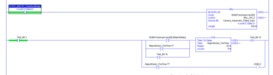
I mention all this because the shift register is a
model used to determine when a bottle with a bad label detected at upstream position
P0 will be at the rejector when the reject has extended to the line of bottles. If the shift register's
discrete movement is tied to the conveyor distance, e.g. to teeth on a sprocket being detected by a prox sensor, then once that fail-bit is in the register it will model the
relative movement of the bottle. The question though is, where is the bottle on the conveyor during the PLC scan cycle when the fail-bit is received?
In slower conveyors, we assume that the variability in the sum of those distances,
Ddetect + Dreject, will be small enough that it does not affect the fidelity of the model and the rejector will hit the right bottle.
For a high speed conveyor, however, that sum of distances make a huge difference.
If you were a quarterback throwing a pass, you would lead a professional wide end by a lot more than you would lead me with my bad hip, even if we were both 10yd downfield at the time you released the pass; the time it takes the ball to travel those 10yd is analogous to the sum of the
tdetect + treject times.
In the time it took me to write this, others have suggested various approaches e.g. adding a timer to model
tdetect + treject. Another approach would be to vary where the code writes the initial detect fail-bit, or looks for the downstream reject fail-bit. Either way, the solution is going to need an empirical approach, because it is essentially adding a fudge factor.


") ?
?
