Stuck on a simple PLC programing problem

neokeelo

Member
Join Date
Feb 2009
Location
Murfreesboro TN
Posts
9
Hello. I am very new into PLC and am still learning basic logic and the commands using the LogixPro 500 software. My teacher assigned us a homework assignment and I am stuck with this problem. He didn't really give us many examples so I'm trying to learn how to make the program. Could anyone help me with the last line?

Here is the Assignment
------------------------------

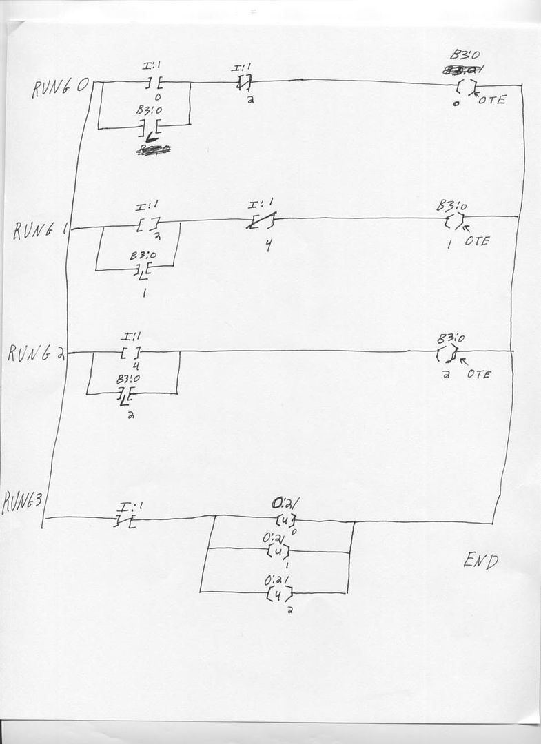
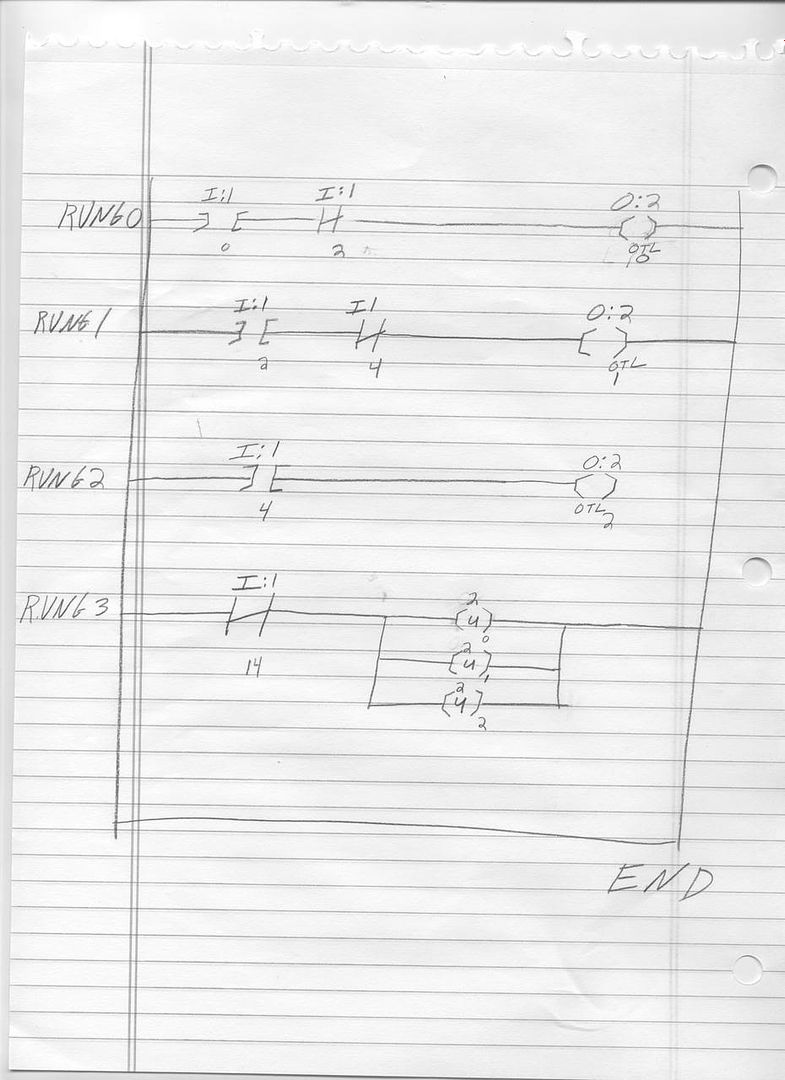
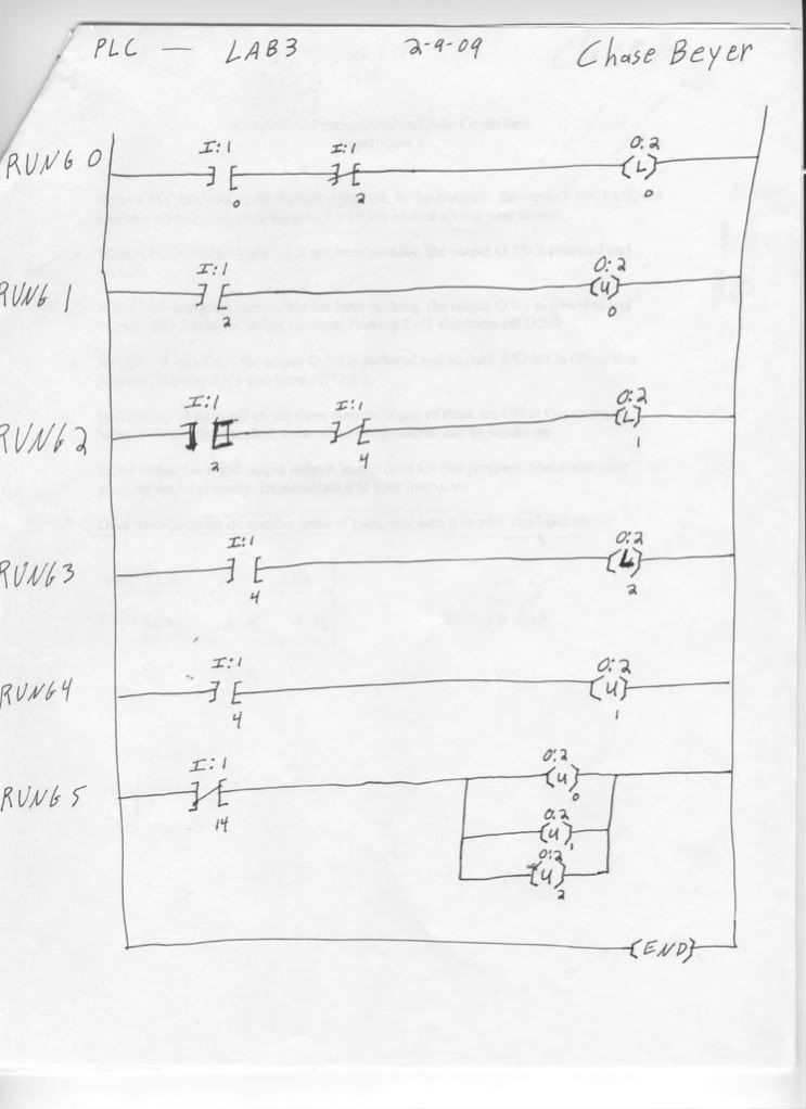
Write a PLC program to do the following task. In the program , the inputs I:1/0, I:1/2, and I:1/4 are normal open push buttons, I:1/14 is a normal closed push button.

When I:1/0 is pushed and I:1/2 is not being pushed, the output O:2/0 is powered and latched.

When I:1/2 is pushed and I/4 is not being pushed, the output O:2/1 is powered on and latched. If O:2/0 is ON at the moment, pushing I:1/2 also turns off O:2/0.

When I:1/4 is pushed, the output O:2/2 is powered on and latched. If O:2/1 is ON at the moment, pushing I:1/4 also turn off O:2/1.

Pushing I:1/14 turns off all three outputs, if any of them are ON at this moment. When I:1/14 is being pushed, none of the three outputs can be turned on.
Use the latch and unlatch command for this program.
------------------------------------------------------------
I attached the program I have written in the attachment. It is a .RSS file.
Ignore the last RUNG, thats where I need help. :unsure:

Any help you can offer me would be very much appreciated!
 
On the last rung, LogixPro allows you to use multiple coils in series ( bad form IMO). RSLogix500 which is the file you posted will not allow this.
Hint: delete the last rung, change the OTL instruction in the other three rungs to an OTE ( the rungs are already self latching)
Then think about where you might put the I:1/14 bit to unlatch those rungs.
 
Last edited:
If I were doing this I would toss the B3 bits entirely.

By 'turn off' do you mean 'unlatch'? They aren't the same thing.

Write the 4 rungs exactly as described. Use only Latch and Unlatch commands directly for the outputs. It's ok to have more than one Latch or Unlatch command for a given output.
 
We should mark and remember this thread. This is a perfect example of how to seek help with homework: clearly state that its homework, clearly state the problem part of the homework, and then show what work you have already done. That is a much better way to learn than asking someone to just give you the answers.

Welcome to the forum neokeelo, we hope to see more of you around. And welcome to the automation world, you're off to a good start.
 
Ok, I think I understand what you guys are saying, but i might still be confused. Your saying I should keep the first three rungs like they are but change the B3: commands to OTE instead and then on the last RUNG unlatch them? Like this?

PLCLab3.jpg


Im sorry im trying to understand better, is there any way someone could draw out the las rung for me so I can see what you mean? Thank you
 
Last edited:
In your first three rungs the output OTEs should be the actual outputs themselves (O:2/1 etc) and should be latches (OTL). Delete the parallel 'B' contacts you have at the start of each.
 
Not quite there yet.

Still need

If O:2/1 is ON at the moment, pushing I:1/4 also turn off O:2/1.


When I:1/14 is being pushed, none of the three outputs can be turned on.

(THis is kind of trick question if you know how the scan works, but I think your teacher wants this at face value.
Think of inhibiting the outputs from turning on)
 
I thought I had it right the first way i drew it out. Also, does the last RUNG not turn off all the outputs the way it is drawn.

I really don't know what to do now...
 
Like I said, you still have to do these 2 requirements
If O:2/1 is ON at the moment, pushing I:1/4 also turn off O:2/1.
and
When I:1/14 is being pushed, none of the three outputs can be turned on.

Yes the last rung does turn them off but technically it does not prevent the 3 outputs from turning on at some point in the ladder.

Do you know the difference between an OTE and OTL/OTU ?
 
Last edited:
Both commands are representations of actual real world devices.

The OTE command mimics a standard relay, if you are familiar with that.

A relay has 1 coil and multiple contacts, some NO and some NC.
The OTE is the same way. Provide power flow out to the OTE coil and it energizes. In the real world providing power to a relay coil energizes the coil, turning it into a magnet that either closes contacts or opens them, thus NO and NC.

The OTL and OTU mimic a latching relay. This is a relay that actually has 2 coils one closes contacts and they remain closed until the 2nd coil is energized releasing a latching mechanism that allows it open back up. You can find relays like this in old time "relay only" pinball machines. So in your program providing power flow to the OTL coil latches it up and the only way to turn it off is to activate the OTU coil.

Hope that helps provide a little more light on the subject. Its easier once you play around with it and see it happen.
 
Thanks for your help guys, after studying some more and fooling around 9 (MUCH) more, I cam to realize my mistakes, if anyone else is having trouble please feel free to study my answer and ask me any questions.

plc3.jpg
 
this is bad practice.
you should never use an output more then once in a program.
Latch a memory place and use the memory in series with your input 14 to stop an output.
if the outputs also should stay off ( meaning releasing 14 would start the ouputs again then also use the 14 to unlatch your memory stuff
 

Similar Topics

Hi Group See the photo. Will this work? I previously had the "contactor outputs used as inputs" tied directly to the IO DIG OUT coils, and what...
Replies
9
Views
1,934
Hi, I am using M221 reading from 3 different sensors (modbus rs485) sharing same bus (daisy chain). I am currently using READ_VAR (in total...
Replies
0
Views
84
I'm using one TON (called SystemTimer) throughout a program that I change the .PRE given different conditions. I'm porting an IDEC ladder over to...
Replies
8
Views
317
We have a keg check weigher that that lost a fight to a forklift. The scale was previously a Systec IT3000, which was the only PROFIBUS slave...
Replies
5
Views
673
really strange issue. The panelview(2711p-T10C22D9P) will try to load an application and get stuck on "Starting Alarms". If I reboot the...
Replies
4
Views
1,448
Back
Top Bottom