linking 2 AB 5/03

Terry Boblitt

Member
Join Date
Jan 2006
Location
Willisburg, Ky.
Posts
119
We currently have 2 blender systems at a pvc pipe factory. I recently made some up grades to one of them using a 5/03 and a 550 interface(2711-K5A2). May do the the other one the same way. It currently has a 5/02 no interface. I know just enough to get the job done---just need some food for thought...The scanner card in the rack is linked to 4 scales using 1 logical rack combined.

#1 I would like to be able to pass data from one 5/03 to the other 5/03. See inputs and also control outputs.
#2 Later on put the systens on the network. Any help (examples to)will be greatly appreciated. (y)

Thanks to all...Terry

Rack configuration=
1746-A13
0-15/03
1-1746-IA16
2-1746-IA16
3-1746-IA16
4-1746-IA16
5-1746-IA16
6-1746-OW16
7-1746-OW16
8-1746-NT4
9-1746-OB8
10-1746-IA16
11-1746-OW16
12-1747-SN
 
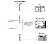
Create a DH485 network. See picture and PDF below for some examples.
Once the network is set-up then use message instruction(s) to pass data to and from your controllers.
I would not try to control outputs thru a communication network though.
Let each PLC do its own controlling.

dh485network.jpg
 

Attachments

  • DH485 Network with PV.pdf
    88.6 KB · Views: 18
If the second 5/03 has an open slot, you could put in a DCM module. It looks like IO to the SN scanner. Can be configured for up to a full rack I believe.
 
You can get most manuals for AB stuff at AB.com/manuals
But basically it is a module that simulates a rack of remote IO to either a PLC5 or SLC with 1747-SN scanner card. You can then have outputs in the SLC that show up as inputs in the SLC with the SN card and visa versa. Outputs in the SN are inputs in the SLC with the DCM. I am using this setup right now on a system with an Ethernet SLC talking to several OEM machines that only have SLC 5/03's. I am also using some pointers to send a block of 20 words for counts from the machines. One word of IO is the pointer and a second is the data it's pointing to.
 
We have a PLC5 talking to four SLC 5/02 processors using the DCM module.

The module supports all A/B RIO baud rates and can be set for 1/4, 1/2, 3/4, or Full logical rack.

The module uses the first word as a status word, leaving the rest of the configuration for data. Ours are all set up as half racks (4 words), leaving three 16 bit words to message with. We use the first of those available for multiplexing to allow us to pass approx. 6 words of data back and forth (using the other two) on a cyclic basis using ladder logic. This is for setting temperatures and modes on air handling units, so it is not time critical I/O

But the DCM would be just as reliable and deterministic as any other RIO if that type of application were involved. It would be a pretty good choice if you want to interlock machines with minimal delays between them, but had too many interlocks to hardwire them all.

It should be easy to add the DCM module to your existing RIO network.

The status bits can also tell each processor about the status of the other one so that you can ensure the rest of the data is valid.

As far as I know, we have had no failures of these ten to fifteen year old devices installed in Nema4 panels on our roof in Oklahoma City. So, like most things RIO, reliability is very, very good.

I would definitely recommend the 1747-DCM.

Paul
 
OkiePC
So---I have a 1747-SN in system #1 which uses 1 logic rack to control 4 scales(1/4 rack each) I will need to install another scanner card and a 1747-DCM in system #2 too? These systems are indenpendent, but I do need to pass some data between between them.
If this is so I assume you can link 2 scanner cards together along with the DCM??
Thanks to all for all of the info.
Terry
 
A 1747-SN can scan up to four logical racks, and you say you are only using one rack. So, you should be able to add a DCM as another logic rack to one of the existing scanner modules. Then extend the blue hose over to the DCM and move the terminating resistor too.

Set up the DCM for the same baud rate and for logical rack 2.

Your existing scales are probably using words 0 through 7 of the scanner, so the area used by the DCM will start at word 8 of your scanner image in both the input and output data tables in the SLC with the scanner.

You could choose another rack number if you desired, and start at a group number other than zero if necessary.

In the SLC that houses the DCM, the addressing will be based on the slot number you stick it in, and will be words 0 through 7 if you use a full rack set up.

If you tell us what slot number you are using for the existing scanner, and what slot you would install the DCM module in, we can give you the exact addresses that they would share...

The DCM is configured with dipswitches, and the manual (available at ab.com) is easy to follow.
 
Last edited:
System # 2 will be a copy of #1 as far as the rack ic concerned except I will replace input card #10 with the DCM card and put another SN carn in slot #12 for my scales.
Been looking at the DCM manual. In chapter 8-basic example is simular to what I will be doing. The pieces of this puzzle is starting to come together. # months ago I installed my first SN card--doing well so far.
This site is great. Ask and ye shall find.
Thanks to all....Terry
 

Similar Topics

So I'm currently in the process of linking 2 1756-L72 processors to send alarms back and forth. One processor is rev 26.13 and the other is 32.11...
Replies
2
Views
124
I have one GE Fanuc IC200PNS002-AC Versamax Network Interface Module and the fault red light is blinking and i have checked in manual it is...
Replies
9
Views
215
I have a Micro820, yes I know they are hated. I have a brand new Micro820 that I programmed with a Micro SD Card. Once I got it programmed, I...
Replies
5
Views
885
Hi, Have very basic knowledge of PLC's. Wondering if someone can point me in the right direction. Our assembly equipment is being run off of...
Replies
7
Views
1,167
Hi, I'm new to working with PLCs and I'm experiencing issues with my WAGO 750-8212 device. When I attempt to turn it on, the SYS LED (orange)...
Replies
1
Views
899
Back
Top Bottom