2 rtd solution

Adam303

Lifetime Supporting Member
Join Date
Aug 2009
Location
Chicago
Posts
587
hi all
I have a 20 foot nitrogen freezing tunnel that i have to do a new control system for.
The tunnel has one electric to pneumatic control valve 4-20 input for the whole tunnel. To have the temperature of the tunnel accurate i need to use two rtd PT100 probes one at the infeed and one at the exit of the tunnel. Using one temp. controller
PROBLEM: Has any one used or know of a device that can collect resistance from both probes and output a avrage resistance. I also looked for a dual input temperature controller but was not able to find anythig of that type.
Thanks for all yor help.
 
Last edited:
hi all
I have a 20 foot nitrogen freezing tunnel that i have to do a new control system for.
The tunnel has one electric to pneumatic control valve 4-20 input for the whole tunnel. To have the temperature of the tunnel accurate i need to use two rtd PT100 probes one at the infeed and one at the exit of the tunnel. Using one temp. controller
PROBLEM: Has any one used or know of a device that can collect resistance from both probes and output a avrage resistance. I also looked for a dual input temperature controller but was not able to find anythig of that type.
Thanks for all yor help.

What is your temperature difference tolerance within the tunnel?

I think you are going to need more than one point ie valve and quite a few more monitoring points unless you are using a wind tunnel type of approach. Because of this I think you should consider a PLC with multiple RTD or Thermocouple inputs and let the PLC do your averaging if that is what you really want.
You would also have the ability to have each sensor ccontrol a valve for that area of the tunnel.

Dan Bentler
 
I totaly do agree with you on this one.
Yes it is a wind type tunnel it has four recirculation fans inside the tunnel.
Temp differance is unknown at this point but i;m assuming it will be about 20 to 30 F just because of the two exhaust fans on each end of the tunnel.

PLc would be a great control for this tunnel.
 
This is for me a classic one.

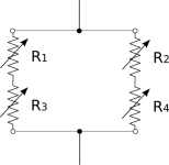
2 rtd give 200 ohms or 50 ohms.
buy another two sensors (they are cheap)
put them in a wheatstone bridge.
now you will have two in series giving 200 ohms and two parrallel making this 200 ohms 100 again.


assumed the cables are not longer as 20 meters there is no big problem.
all sensors are averaged
use only two wires on each sensor and take all 8 wires to the controller for easy measurement.
 
If you really want a stand-alone PID temperature loop controller, the Honeywell UDC 3500 can take two RTD inputs, and with its Math option, average the two RTD temps or do a weighted average of the two (like 60/40 or whatever); the result of which (the average) then becomes the process variable (PV) of the loop. A 4-20mA current output will drive the modulating valve.

It isn't clear to me that averaged temp is what will work to satisfaction, but the UDC will do that for you.
 
This is for me a classic one.

2 rtd give 200 ohms or 50 ohms.
buy another two sensors (they are cheap)
put them in a wheatstone bridge.
now you will have two in series giving 200 ohms and two parrallel making this 200 ohms 100 again.

That's a pretty slick solution. It took me a minute to realize you meant to arrange the sensors in a parallel-series fashion as you would in a wheatstone bridge, not to actually use the output of the wheatstone bridge.
 
Last edited:
In thinking a little more on this, the RTDs that are in series with each other should be on opposite ends of the tunnel to get the most accurate average.

In the attached drawing, R1&R2 would be at one end of the tunnel and R3&R4 would be at the other.

resistorbridge.png
 
Clever scheme. The wire resistance will appear as a constant offset, so the 'input' could easily be calibrated by having all the RTDs at the same temp (stick 'em in an ice bath) to find the offset.
 
In thinking a little more on this, the RTDs that are in series with each other should be on opposite ends of the tunnel to get the most accurate average.

In the attached drawing, R1&R2 would be at one end of the tunnel and R3&R4 would be at the other.

I do not see any advantage of placing four sensors and then connecting them to derive an average reading. I do see some disadvantages
1. Cost - one sensor could be placed to get same result
2. There is no way as designed to discriminate between the four measured zones
- one could be very high and another very low
- the average would be the same.
3. I believe if one is to use four sensors then best advantage is to be able to monitor each individually.

Dan Bentler
 
Hi im an engineering student and just got introduced to plc's. I have done my research but i want more information about a automatic car park system operation using a plc. anyone who can help me pls do so.
 
Dan,
>I do not see any advantage of placing four sensors

The advantage is producing a single, nominally 100 ohm RTD circuit that can be used as a PV input for one PID loop using a single modulating valve.

>designed to discriminate between the four measured zones

There are only two zones, infeed and exit zones. The idea is to average the two readings. The additional two RTDs are there for purposes of creating a single, 'proxy' 100Ω RTD circuit (100Ω + 100Ω in parallel with 100Ω + 100Ω = nominal 100 ohms) that averages both the infeed and exit ends. In fact, the two 'like' RTDs at each end should be a dual element RTD style that will give a reading very close to its mate in the same sheath.

I agree that presumably one temp could be very high and the other temp very low, with the 4-RTD circuit giving the arithmetic average of both.

Is an average temp value what's needed for control? Maybe, although the infeed temp could be used as feedforward in a single PID loop if the infeed temp should change for some reason.

Dan
 
I do not see any advantage of placing four sensors and then connecting them to derive an average reading. I do see some disadvantages
1. Cost - one sensor could be placed to get same result
2. There is no way as designed to discriminate between the four measured zones
- one could be very high and another very low
- the average would be the same.
3. I believe if one is to use four sensors then best advantage is to be able to monitor each individually.

Dan Bentler

His original request was to take measurements at 2 zones and use the average from both zones to use as the Process variable, so the sensor bridge matches the specification nicely as far as I can tell.

The cost of two additional RTDs is relatively cheap compared to some of the other solutions being posed.
 
Adam,
Another solution would be to use two Type "T" thermocouples. You can place the two of these in parallel and they will average out the temperature. If you use an exposed tip style TC they will respond faster that an RTD in free air due to the thermal mass of the construction of the RTD. Types “T” are stable and good for cryogenic applications.

Also if your probe is vibrating in the wind tunnel your RTD may be short lived depending on it's construction. Wire wound RTD's do not like vibration at all.

Just use a T/C card instead of an RTD card, or a 4-20 mA T/C transmitter.

Be carful averaging two RTDs since the resistance curve is non-liner. It might affect the accuracy more than you think.

For the record I usually prefer RTDs but there are some application where TC are good or better match.
 
At the end of the project, I would be willing to wager that he ends up needing more precise control of the output temperature, while the input temperature will probably be useful as a feed-forward. For that reason, I would not hardwire them for averaging.

If you need the average, you can still do that with very simple math, but leaving them as separate inputs will give the programmer maximum flexibility.

JMHO
Paul
 

Similar Topics

I have a 20ma output card and a Thermocouple card which also can be configured to 0-100mv. I need a remote temperature sense. There are control...
Replies
3
Views
3,019
Just wondering if anyone has come across any RTD cards for Control Logix with higher than 16 bit resolution.
Replies
8
Views
5,563
Good Morning , I have a RTD , that I would like to wire into a 1756-IF8 Analog Input Card. Would you all a simple wiring diagram , of what...
Replies
4
Views
1,201
Good Afternoon , It seems like we always have problems with using Type J Thermocouples with our slip rings . Would using a RTD at 10...
Replies
6
Views
1,644
We are running a power flex 70 connected to a Delta V and I cannot get the drive to start because I am getting a STOP ASSERTD message on my HMI. I...
Replies
4
Views
3,047
Back
Top Bottom