CIMPLICITY problem

Guest

Guest
G
Hi all!

Well, since i'm new here i'll just shoot my Q! Hope someone A's it :)

Thing is i'm making a program for fermentation ... but that's not important!

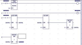
I made a program which outputs 4 signals in bcd inc. like

0001, 0010, 0011, etc. to 1010

i attached a pic.

but the problem is ... that my output is just opposite than it should be.

instead of 0001 | 0010 | 0011 | 0100 | 0101 | 0110 | 0111 | .. IS
1000 | 0100 | 1100 | 0010 | 1010 | 0110 | 1110 |

If anyone can help me out ... please do :)
At least do it for the sake of my nerves :D

TNX in advance,

Moose
 
I think your programming software is set up to display binary references with the LSB on the left instead of on the right. Or else, if you're looking at the LEDs on the face of an output module, %Q001 is to the left of %Q0002 which is to the left of %Q003, etc.

BTW, in your program, rung 2 is unnecessary. %M0005 will be true for one scan every time the timer reaches preset.
 
Last edited:
Actually, the program is helping you out.

In rung 4, you moved the integer value in R154 into an address at Q1, which is the first real output (if so configured).

What you REALLY did is map the 16 bits in R154 to the 16 output bits beginning at Q1. In other words, that integer move set the value of the first 16 outputs.
 
Steve: The thing i want to find out is how to reverse the outputs. in other words how to make MSB a LSB .. and LSB a MSB.

Oh i know about the 2nd rung ... it's just for my mentor.
 
Let me get this straight. Are you claiming that, in your example, when %R154 contains a decimal value of 8, that %Q0001 is on and %Q0002, %Q0003, and %Q0004 are all off???

Otherwise, why would you want to reverse the order? I can't think of any single instruction in the GE Fanuc function set to reverse the bit order. You can always use the 'brute force' method:

_____
| MOV |
------| INT |
| |
%R154 | |%M001
|_____|

%M001 %Q016
--] [----------( )-

%M002 %Q015
--] [----------( )-

etc.


But once again, why?
 
Steve! You're the man!! :)

I was thinking of most complex ways to reverse the output ...
and didn't even think of "brute force" :)

The thing about reverse outputs is that my menthor told me to do the program ... i made it .. but because the outputs were from Q1 to Q4 instead from Q4 to Q1.

So now you know you helped a LOT ! :)

P.S. I O U 1 :D
 
Steve: about the 1st question ... when in %R154 are numbers from 1 to 10 (incrementing) on outputs are the right values but my program must have the outputs reverted.
 
This sounds like byteswapping to me. Have you tried the ROR WORD function?
Peter
 
Peter : yes i've tried ROR but the function only puts Q1 to Q13, Q2 to Q14 etc.

and what i needed was ... Q1 to become Q4, Q2 - Q3, Q3 - Q2 and Q4 to Q1

But Steve helped me out already ... TNX anyway :)
 
Steve: Oh .. I have this project in which outputs must be from Q1 to Q4 and they represent binary values from 1 to 10. And if it would be just for me and my boss i'd probably do it with rewireing, but i must make a version that a certain firm wants so my hands a tied (so i can't get to wires :) )

but do not worry ... everything went smoothly with your help :)
TNX again ! :cool:

p.s. if you really want to know .. the outputs are connected to incubator and levels from 1 to 10 represent the action that incubator is performing .. i.e. when level 3 (0011) is reached, valve no.3 opens and it washes the bin ... that's why i can't mess with outputs.
the firm preset the outputs to be Q1 Q2 Q3 Q4.
so you see how certain people can make my life miserable :)
 
BCD to Integer

In your first post you said that you wanted BCD, well there is an integer to BCD conversion block in Cimplicity ME, it will do what you need.
 
First GE has a INT_BCD command that you could use to convert the INT to BCD if wished. More importantly you are moving a 16 bit INT into outputs with a length of 1, this can be done easily enough but wont you end up putting the last 4 bits (the ones you want) in q13 to q16. Try using the Move BIT instruction with a length of 4.
 
Russ, DesertDog,

I don't think this is about converting between integer and BCD. Check the sample logic that ACF posted. He's got a counter that runs between zero and ten and then resets itself. Then he's taking the accumulated value of the counter and moving the bit pattern to real-world outputs. The problem seems to be that the pattern of real-world outputs is neither BCD nor binary, but a mirror image of binary. Converting from integer to BCD will not help. Converting single-digit values from binary to BCD does absolutely nothing. ACF said he had a problem with all values, not just when the value was 10.

ACF, you could also use this equation to create a mirror image of the four bits:

(%R154 AND 8)/8 + (%R154 AND 4)/2 +(%R154 AND 2)*2 + (%R154 AND 1)*8

but I think the method I gave you earlier is simpler.
 

Similar Topics

After changing a windows password of the session where we are running a cimplicity project we are no more able to write values to the PLC. In the...
Replies
3
Views
1,559
Hi I have problem with cimplicity 7.5 can any buddy help me regarding this. Actually I am using a cimplicity 7.5 as a SCADA and Delta PLC...
Replies
0
Views
3,759
Hi All in table logging attribute tab i checked for on digital point high for virtual point. but when i change this point from 0 to 1 no data is...
Replies
0
Views
2,263
Dear All, i am facing one Ethernet communication problem with versamax system and cimplicity 7.0 in Hyderabad site. The system has got 2 versamax...
Replies
1
Views
6,284
When I want to connect to another computer that has Proficy projects running, an error meassage appears: "You don't have correct OS rights"...
Replies
2
Views
3,492
Back
Top Bottom