Determining Analog input card error

James Mcquade

Member
Join Date
Oct 2007
Location
Nashville, Tennessee area
Posts
3,680
Hi everyone,

Our company has had a problem with a vendors machine, it keeps failing parts. As we all know, no one makes bad parts so its got to be the vendors machine.

I was asked to look into the electrical part of the test machine and did discover several problems and fixed them.

By doing all this, the machine now operates much better. Now the quality department has made this machine a six sigma project and wants me to write up everything. that parts ok.

How do i tell the quality bunch what the error associated with
the analog input card is?

I have an AB 1746-NIO4I card. (2) 4-20 ma inputs and (2) ma outputs. Looking at the specs is greek to me when i have to take all the associated errors into consideration.

Any help would be much appreciated.

thanks in advance,
james
 
survival tip: don't try to reinvent the wheel on this one ...

has this six sigma program already been up and running for any period of time? ... if so, see if you can dig around and come up with an existing similar report that the quality department finds "acceptable" - and use that as an example ... then plug the specs of your module into that same format ...

basic idea: it's a lot easier to hit the target - if you know exactly what the target looks like ...

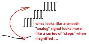
going further: if you can put your finger on the part of the specs that you find most confusing, we'll try to help you understand them ... in the meantime, the sketch below might help you with the basic concepts of "analog" signals in a "digital" PLC ... the truth is that there is NO true analog signal in the PLC - just a series of very small "steps" ... understanding "how many" steps there are - and "how much time" occurs between each step - is a big part of getting a handle on this particular subject ... looking up "successive approximation" might be helpful ...

big picture: the PLC processor doesn't know EXACTLY what value the "analog" signal represents - he just knows that the signal is BETWEEN "this" value - and "that" value ... sort of like the old "guess my number" game ... (no, too high - no, too low) ... once you've got the picture in your mind, understanding the specs will be a lot easier ...

analog_steps.JPG
 
Last edited:
Ron,

if you look on page 24 of the installation manual, publication 1746-in008c-en-p, you have the over all accuracy at 77 degrees, the overall temp accuracy for the full range of operation, the gain drift, gain error, offset error, and temperature error.

when i talk to the local rep, he can't give a good answer, but
he does better than the ab guys using our tech connect number.

i am trying to understand what i really need to look at and pay attention to. this will come up again i know and i need to remember and put it on paper / save it on the pc for the future.

thanks,
james
 

Similar Topics

We are in the process of installing a new DC drive to replace a 1373 series Speedpak drive. There are 8 leads coming out of the motor -- Two for...
Replies
5
Views
845
Good morning! I am looking for a clever method to determine the number of occurrences in a series using ladder logic. What I need to determine is...
Replies
6
Views
1,259
I have my PLC and HMI connected to my local network over DHCP just like my laptop. I can upload and download including VNC to the HMI over wifi...
Replies
2
Views
1,138
We have a DC Drive (ABB DCS800) which is running a load (initially) at a fixed speed. For testing purposes, we want to simulate a different...
Replies
20
Views
6,263
ive been tasked, due to a restructure of our inventory, to find out how big our SLC programs are. specifically, we have several dozen 5/05s at...
Replies
4
Views
1,707
Back
Top Bottom