Stacking Load Cells?

ndzied1

Lifetime Supporting Member
Join Date
Aug 2002
Location
Chicago, Illinois
Posts
2,857
I have a customer that is trying to calibrate a load cell in a system by putting another load cell into that system and seeing if they agree. Each load cell is independent from the other.

The picture shows the basic mechanical layout of what they are doing.

My theory is that if I assume that the mechanics are perfect (no friction and perfect alignment of components, no deflection of components, etc.), that if they are reading 1000 LBF on each of the transducers, that the cylinder is pressing with 2000 LBF force. They are thinking that the same force goes through both transducers so that the cylinder is only pressing with 1000 LBF force.

I have asked them to take pressure readings at the cylinder to confirm or disprove my theory but in the meantime, wanted to get some feedback from others.

This came about because the two reading agree up to a point and then diverge. My thought is that with the force doubling that the system is running out of pressure or starting to deflect. They don't want to believe me.

Thanks.
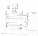
LoadCell.PNG
 
They are thinking that the same force goes through both transducers so that the cylinder is only pressing with 1000 LBF force.
This is correct.
They would be additive if in parallel and sharing the load. In series they both see the same load.
 
Your customer is correct.

Look at your drawing. Load cell #1 is between the cylinder piston and the load. Therefore 100% of the force applied by the piston is applied to load cell #1. There is no magic short cut that the applied force takes - the force must be transferred to the part by load cell #1.

The apparatus drawing shows load cell #2 is not axially aligned. Cantilever beams transfer the load. You can think of the cantilevered beam as a spring that absorbs some of the load and transfers some of the load. That means that the load cell #2 will receive a slightly lower force.

I would say based on the info so far the apparatus is less than ideal for calibrating the load cells.

BTW, when using cylinder pressures to cross check a reading be sure to include both the piston blind side pressure and the piston rod side pressure. Force = (Cylinder_Area*Piston_Blind_Side_Pressure) - ((Cylinder_Area-Rod_Cross_Section)*Rod_Pressure)
 
Last edited:
I would say based on the info so far the apparatus is less than ideal for calibrating the load cells.

No one would dispute that.

I found the error in my thinking which was that I had assumed that springs in series add like resistors. However, they add like capacitors.
Code:
 1/K_total = 1/K_1 + 1/K_2.
BTW, when using cylinder pressures to cross check a reading be sure to include both the piston blind side pressure and the piston rod side pressure. Force = (Cylinder_Area*Piston_Blind_Side_Pressure) - ((Cylinder_Area-Rod_Cross_Section)*Rod_Pressure)
That much I had correctly :)

Thanks for the help over my brain ****!
 
Norman that all sounds good but how do you know if ethier cell is calibrated with this method seems if you have one known calibrated cell it would be easier to just replaace one with the known good one. isn.t this done with known weights. just new to this and have never seen it done this way. Thanks,steve
 
Well, there is calibration and there is calibration.

This is my customer's customer doing this and I have not much control over what they do or why.

My feeling is that they are trying to get a rough idea that the thing is working. They are not trying to determine accuracy or repeatability to any specific value. Physically removing and replacing the load cell is not an easy task and they don't want to do this if they don't have to.

The started taking measurements with the machine set at different forces and the readings agree at low force but after about 50% of the capacity of the system the machine load cell is reading higher than the "calibration" load cell and the two lines are diverging.
 
The started taking measurements with the machine set at different forces and the readings agree at low force but after about 50% of the capacity of the system the machine load cell is reading higher than the "calibration" load cell and the two lines are diverging.

That is pretty much what I would expect to happen with those cantilevered beams.
 
This is a fundamental statics problem, not a controls or load cell problem.

The upper cell does indeed take 100% of the cylinder load. It should read F = p x A where p is hte cylinder pressure and A is the cylinder area.

It looks to me like the lower load cell isn't going to take the full load. It would appear that the upper shaft is supported at the left side. The load cell off to the right would then take at most half the load, and less than that if the upper shaft is indeed held rigid and acting like a spring.

The upper shaft is in a block that rides up and down on a large set of linear bearings. The system is pretty rigid but no system is perfect and we are talking a 5" bore cylinder so close to 40,000 lbf at 2000 psi. They had assumed:

  • that the upper block moves perfectly straight up and down
  • that there is no friction in the system
  • that nothing in the system bends
  • that the button on the load cell can apply the force exactly on the central axis of the cell.
That is a lot of assumptions!

But my stupid tangent about double the force led us down the wrong path for a while.
 
The assumption that gets you in the most trouble is that nothing in the system bends. The upper platen of the die set will elastically bend and also the cantilevered beams connecting to load cell #2 will elastically bend. Also if anything is in the die set (tooling/parts/etc.) it will take part of the load.
 
This thread reminds me of a time when we made a drilling/ spotfacing machine with a hydraulically driven head. The position feedback was in the cylinder.

The depth tolerance for the spotface was pretty tight and the customer complained that over the course of the day, the depth would get deeper and deeper and eventually go out of tolerance. They told us the controller was drifting and all sorts of things.

When I told my boss I thought the rod of the cylinder was growing he thought I was crazy. When I did the calculations based on the cold vs. warm oil temperature and the expansion coefficient of steel and they were close to the measured changes he thought I was on to something. When we put on a new external feedback and all the problems went away he gave me my next project 🤾
 

Similar Topics

Hey all, running into some trouble trying to get this done cleanly. I have two inputs of 16 bytes each, from two different locations. I take both...
Replies
1
Views
2,015
I have an application with output stacking. The applications is: 8 conveyors merge into 1 each of the 8 conveyors have a photocell each...
Replies
2
Views
2,824
Hey Guys, I'm trying to come up with programming(Contrologix) for alarm reporting. The alarms are to be stacked(I'm thinking FIFO)and recalled one...
Replies
61
Views
12,975
Hello, I have 8 different numeric values shown on a PV550 in a row as "Numeric Values". From the PLC I want to control the HMI so I can indicate...
Replies
9
Views
2,680
I am running CCW 13 trying to upload to a micro 820 vers.12 I get an output message OPC server is unable to load project controller. Please help!
Replies
5
Views
231
Back
Top Bottom