electrical motor

ajay34

Member
Join Date
May 2010
Location
klang
Posts
249
hai guys..:geek:..

i m having some issue with electrical motor again which using auto trans stater ..which this time it not my own panel insted it was given from other plant and send to us to fix it ..and the diagram was made by my senior manager..

problme now..when start the motor without load it seem working good but than when we increass load into it ..it just start to triping at 200amp more or less..
i do find something really wrong with the diagram and wiring made ..but than the other team claim it was working good for them until they ship out to us..

normally when i made my own auto trans stater..
auto trans contactor would not remain on when delta contactor are in ..but this diagram show the otherway round and i m confuse seem my senior manager cant understand what language me talking too him..(i guess)

can you guys have look and correct what wrong it ..
as far i see the TC are remain on even when MC are cut in which tc supply still the and output 65% tapping from auto trans.
 
hai ..i have the diagram ..but it say 600kb..how could i make it 300kb..as it was on pdf ..sorry guys i m not really good in zip file..


please do see attacment ..somehow i think i able to send it now
 
Last edited:
I do find something really wrong with the diagram and wiring made ..but than the other team claim it was working good for them until they ship out to us..
That wiring diagram from "Mr. Mark" appears flaky. The Main Contactor is wired so that it will drop itself off (from the MC normallly closed contact on the first rung). The diagram is wrong, or some information is left out (5C could be a Latching relay, but I see no way to unlatch it).

I also think the Start and Stop button labels are switched. Stop should be moved to the first left button, which appears to be the Normally Closed contact that is used for Stop pushbuttons. It would more likely Stop the motor in this position.

Is this a test?
 
Last edited:
That wiring diagram from "Mr. Mark" appears flaky.
I also think the Start and Stop button labels are switched. Stop should be moved to the first left button, which appears to be the Normally Closed contact that is used for Stop pushbuttons. It would more likely Stop the motor in this position.

I agree that the start and stop buttons are wrong.
However (allowing for that) the circuit seems to work!

The start button is pressed and TM AND SC energise via the normally closed of MC.
TC will energise via the normally open of SC, the normally open contact of TC acts as a hold on for TC, SC & TM.
When TM Times out (assume it is a timer) then SC will de-energise via normally closed of TM
MC will now energise via the normally closed of SC and the indicator lamp will come on via the normally open of MC

Pressing the stop button will de-energise all coils.

Perhaps "Mr Mark" could comment!!!!
 
Last edited:
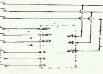
I do not know if I'm being overly critical. The "box" depicting the auto transformer appears to have a 80% tap to one "T" lead a 60% tap to another "T" lead and a 65% tap to the last "T" lead.

blackbox.jpg
 
...MC will now energise via the normally closed of SC and the indicator lamp will come on via the normally open of MC.
No, there is one more step. When MC energizes, the little MC normally closed contact on the top right (first rung line) goes open, dropping out SC, which drops out TC, which drops out MC!. Then (if it was really wired this way), the cycle would repeat, ON, OFF, ON forever. There is still an errror somewhere, a line missing, or a contact in the wrong place, or mis-labeled.

Or the line from the 3rd branch, right of SC NO, down to the indicatior light, is supposed to have a " . " on it where it crosses the line to MC. In other words, once TC is energized, it seals itself ON, until the STOP button (labeled START) is pressed. But without that DOT indicating a connection, the diagram AS IS is not correct, according to most common wiring standards here in the US.

As far I see the TC are to remain on, even when MC is cut in, which will supply still the output "65% tapping from auto transformer".
Yes, if the wiring diagram is corrected, then SC will go OFF, but TC has to seal itself ON to keep MC ON. The usage of TC and SC may have been rewired and swapped (switched one for the other) at some time in the past.
 
Last edited:
problme now..when start the motor without load it seem working good but than when we increass load into it ..it just start to triping at 200amp more or less....

do this problem (wrong) wiring will coz the above problem appear?..
thanks on the comment guys..now my senior manager wonder why the other plant claim it can work and waiting for their ..i share to him all ur comment..
 
it just start to triping at 200amp more or less....
Check the Overload. The overload could be worn out, so that it trips at a lower current than it should. If you have a spare Overload relay, install that and test it.

If the overload is good, then your motor could be weak, with the winding insulation failing. Often that shows up as an intermittent problem, sometimes working, sometimes not. Bad winding insulation can also show up when a motor is moved from one location (with slightly higher voltage and current available, to a location with a slightly lower main supply voltage (or it is being fed from a main transformer with a lower capacity).

do this problem (wrong) wiring will coz the above problem appear?..
Probably not. With TC energized, the autotransformer winding is still energized, but when MC goes ON, it bypasses (or shunts) the lower voltage from the autotransformer, so it has no more effect. It would be less heating for the autotransformer if it was removed from the circuit, but even with it on, it should not change the starting of the motor.

One thing you could try is to slightly increase the time for the TM timer. Leaving SC in longer should allow the motor longer time (at lower voltage) to get to full speed.
 
Last edited:
...the auto transformer appears to have a 80% tap to one "T" lead a 60% tap to another "T" lead and a 65% tap to the last "T" lead.
Milldrone, that is a relevent point. I bet the autotransformer has really 4 taps, a 0% for the center phase, and 80, 65, and 50% for the other two phases. The voltage can be adjusted for different motors and different loads. That would be another method to try to keep the motor from tripping. The autotransformer output could be moved to the 50% leads to allow longer time at lower voltage, in the hope of getting it up to speed at a lower current level.
 
Last edited:
No, there is one more step. When MC energizes, the little MC normally closed contact on the top right (first rung line) goes open, dropping out SC, which drops out TC, which drops out MC!. Then (if it was really wired this way), the cycle would repeat, ON, OFF, ON forever.

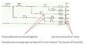
I read it differently - the normally open contact of TC is the "hold on" contact for the coil of TC and MC?
Then the circuit will work - apart from the start & stop buttons being the wrong way around.

cct.jpg
 
Last edited:
I read it differently - the normally open contact of TC is the "hold on" contact for the coil of TC and MC?
Yes, that is the way it is SUPPOSED to be. If I was the engineer checking this drawing, it would be covered in red marks. Sometime along the way, draftsmen started taking all these shortcuts. Still doesn't look right to me without connection dots at connection points, but then I am just an old guy living in the past glory days.
 

Similar Topics

Hello all, I am on the phone to someone who is remotely trying to diagnose a motor problem it is a 30kW 4 pole, 400VAC ABB motor connected to a...
Replies
40
Views
11,069
Hello, I'm trying to get a blower motor to run in the field. I had an electrician provide 100A single phase 230v service. This service was...
Replies
28
Views
7,710
Could anybody help? Where can I find IEC standard about Electrical control panel ,plc,motor in pdf format? How much does it cost? Thank a lot...
Replies
4
Views
10,038
Hi everyone, I'm in search of software for electrical drawings, preferably free but also interested in paid options. Any recommendations or...
Replies
33
Views
1,576
Back
Top Bottom