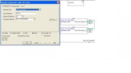
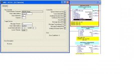
MSG Instruction Help...

The MSG block is reading 25 integer addresses from node 1 (another PLC?), starting at N215.0 (N215.0 to N215.24)and placing the values it finds into the calling PLC's data table N112.25 (N112.25 to N112.49), this transfer is over PLC channel 1 which is the DH+ comms link - the N12.0 is the control block which contains the status, error codes etc for the MSG block, which in the case of RSlogix500 is 14 elements long, which means it occupies N12.0 to N12.13 (if using multiple MSG blocks be aware that N12.0 to N12.13 have been reserved and offset your next MSG control block (for instance N12.15 to N12.28)).
It is much the same with RSLogix5000 accept it places the data into the specified tags array (CIP1_read_buffer(0))
Note!
These receiving data table addresses must be already created in in the PLC's or a Fault will occur.
Another type of MSG is a write which does what it implies and writes to another PLC using much the same protocol as the read.

Steve
 
Thank you for the explanation. My confusion is even greater now because if I'm not mistaken "500CPURead" on the communication command implies that this other PLC is SLC500, correct.

When I go to this other PLC which I think is the one is talking via DH+, I can't find an N215 register in it.

There are only three PLC talking in this system, two are SLC 5/04 and another is a ControlLogix.

Perhaps I need to look at the node addresses to correctly identify which PLC's are involve in the exchange of information.
 
The MSG block is reading 25 integer addresses from node 1 (another PLC?), starting at N215.0 (N215.0 to N215.24)and placing the values it finds into the calling PLC's data table N112.25 (N112.25 to N112.49), this transfer is over PLC channel 1 which is the DH+ comms link - the N12.0 is the control block which contains the status, error codes etc for the MSG block, which in the case of RSlogix500 is 14 elements long, which means it occupies N12.0 to N12.13 (if using multiple MSG blocks be aware that N12.0 to N12.13 have been reserved and offset your next MSG control block (for instance N12.15 to N12.28)).
It is much the same with RSLogix5000 accept it places the data into the specified tags array (CIP1_read_buffer(0))
Note!
These receiving data table addresses must be already created in in the PLC's or a Fault will occur.
Another type of MSG is a write which does what it implies and writes to another PLC using much the same protocol as the read.

Steve

Don't want to get too pedantic, but the correct addressing uses a colon between the file and element numbers....

starting at N215:0 (N215:0 to N215:24)and placing the values it finds into the calling PLC's data table N112:25 (N112:25 to N112:49) etc.....

Just want to make this clear for anyone else reading the thread
 

Similar Topics

Hello All, This might be a simple question for most of you. I am working on performing some tests on an EIP device through RSLogix 5000. Based...
Replies
7
Views
2,040
Hi, I'm trying to ensure I have the correct path to allow msg read from 5380 processor via compactlogix. The SI has installed it in a way I'm not...
Replies
12
Views
6,506
I'm trying to use a MSG instruction to get data from a SLC into a ControlLogix. I want to read some Boolean tags from the SLC. Is it possible to...
Replies
4
Views
2,852
Hello all. I need some help setting up a MSG instruction to transmit 10 bits of data from a compact Logix processor to a micrologix 1400. I have...
Replies
31
Views
20,041
Good morning everyone. I'm relatively new to the Allen-Bradley world. My issue I'm facing is this. I have a remote Refractive Index sensor...
Replies
2
Views
2,252
Back
Top Bottom