Noise Filters for Analog Inputs

Lancie1

Lifetime Supporting Member
Join Date
Jul 2003
Location
Alabama
Posts
9,999
I need some help with this situation: I am writing an A.B. SLC 5/02 program for handling scrap metal. I have an ultrasonic level detector, mounted underneath the swiveling discharge chute, that is supposed to tell me when the scrap metal bin (approximately 6' W x 22'L x 6'D) is full. However, the equipment supplier has said that the ultrasonic detector will also pick up the noise made by the irregular pieces of metal falling into the bin. How can I best filter out the noise and leave the bin level signal (0 - 10 vdc)?
 
Last edited:
Sounds like ultrasonic is not the way to go in this application, for the reason you stated.

I once tried using an ultrasonic sensor to measure the level in a vibratory feeder bowl feeding metal overshells (outer aluminum shell for mascara tubes). BIG mistake! When the bowl was on, the sensor went crazy. I switched to a photoelectric sensor, and all was well... 🙃

beerchug

-Eric
 
Eric,
Thanks, may I quote you to the equipment manufacturer (PRAB), who insists that the ultrasonic is the best, even though he admits it will pick up noise?

We am installing as a backup sensor, two simple 24 vdc wire probes hanging in the bin to make a circuit when the scrap gets high. But still I have been told to make the ultrasonic sensor work, because the bins (there are actually two, Bin A and Bin B) are sitting on a slope, and the wire probes will move with the discharge chute, so the bins will not fill evenly unless the ultrasonic level detector is made to work.

The ultrasonic sensor puts out a 0-10 vdc signal proportional to the distance between the scrap height and the sensor. I have the signal tied to an encoder signal so that I can adjust the "full" level as the discharge chute swivels from 0 to 100 degrees in each bin, thus adjusting for the unlevel bins.

Now does someone know how to write a PLC filtering routine that would remove part or most of any extra signal due to noise?
 
I love when the spec. calls for an item that's wrong for the application... :rolleyes:

I don't know which way your sensor operates, so let's say 0V is the 'empty' end, and 10V is the 'full' end of the sweep. Let's also say that >8V = "Bin Full".

The falling pieces may give you INTERMITTENT readings >8V, but they shouldn't give CONTINUOUS readings >8V. Therefore, you should be able to just add an on-delay timer to ignore the intermittent readings. If the reading stays above 8V for say, 10 seconds, you can assume the bin is REALLY full.

beerchug

-eric
 
In addition to Eric's suggestion for a delay timer, I suggest that you filter the analog input signal in the SLC program. Its easy:

New Filtered value := (Raw analog value - Old Filtered value) / Factor + Old Filtered value

A factor of 3 will provide sufficient damping of the signal.
Do not exceed a factor of 5 for integer math (the SLC5/02 doesnt have floating point math I think).
 
Sorry Jesper, Eric has the right answer.

That is because the 'noise' is NOT noise. It is just bad readings caused by falling scrap metal. Noise should be random but the falling scrap metal only only cause high readings that will falsely say the bin is full. If you apply the digital filter, the false readings will give a high bias and trigger the bin full too early.

When I have come across problems like this I sometime use a filter like you suggest BUT I use two time constants. One faster rate for those reading below the filtered averaged and a slower timeconstant for those readings above the filtered average. In addition, I put limits on the value that gets averaged in. There is no point in filtering a value that is so far from the expected value that it will greatly affect the filtered value off.

See my other posts about filters and time constants.

If the goal is just to get a bin full indication, Eric's solution is simple and will work well.
 
Can you give the model of ultrasonic level detector you have.
The type I use have a microprossessor that has parameters for filtering and dampening. (Milltronics Multi-Ranger)
 
Peter,

I read your post and dont quite understand it.
Do you mean that the beam of the ultrasonic sensor "looks" thru the stream of material falling into the bin ?
If so, you are quite right that filtering cannot do it alone. I would consider to place the sensor where it has a free view down into the bin if possible.

From the original post, I figured that the problem was that the sensor picks up the audible noise and interpret that as false readings. I have experienced something similar with an ultrasonic "switch" that gave false signals when someone used a hammer nearby.
Being in the foundry business i know very well what infernal noise it makes when you drop castings (or scrap metal) into a bin.
 
Thanks, Guys,
I knew I would get some good ideas. I will try to respond to all your comments. Sliver, I don't actually have it yet, still in design stage, but it will be a Banner Engineering Corp. #SUA923QD, supplied by the conveyor equipment manufacturer, so I cannot change it at this point.

Eric, I like the timer idea. I have put it in the program already. Jesper and Peter, I have decided to go one step farther and try to filter out everything that is not "signal". So I asked, what do I know that would eliminate High and Low values that cannot be the Bin Level Signal? I know the maximum scrap fill rate is 28,000 lb per 8/hour day (conveyor design rate). I know the bin size, and so I can calculate the maximum bin fill rate. Theoretically it will be 0.1 inches/second, so I automatically doubled it to 0.2 to allow for the "real world" unknown factors. I will have to verify this in the field once it is running, and adjust the fill rate factor as necessary.

Now I have a slope of a line, and I will set up PLC calculations as follows: Fill Rate = Absolute Value of [(New Input value - Old Value) / (Time2 - Time1)], where the delta Time will be a constant 1 second, every time the DONE bit goes high. If Fill Rate <= 0.2, then New Filter 1 Value is a Good Signal, otherwise, forget it!

Now if it still doesn't stablilize, then I will take Jesper's idea and say: New Filter 2 Value = [(Old Filter 2 value X "1") + New Filter 1 Value] / 2. Jesper if that doesn't do it, I will change the "1" in the equation to a 2 and change the divisor to a 3, and so on until it looks clean, or until I bump against the 32767 integer number limit. So what do you think? Will this do the job, or am I tilting at windmills?

Has anybody had this type of filtering problem with reading negative pressure in an oven or boiler, where you have to maintain -0.2 inches WG pressure to prevent fumes and smoke from getting into the control room?
 
Lancie,
does the Ultrasonic sensor have some kind of filtering built in ?
If so, you should turn it OFF if you want to use your method of cleverly sorting out false readings.
The reason is that you are testing the rate of change to detect the false readings, so you want the signal to be as raw as possible.
I am not sure that it is possible to do as you suggest, but I think that there is a good chance. There has to be a certain amount of good readings when the bin is filling in order to extract the good data.
The question is if the ultrasonic sensor is completely freaked out when there is noise from the falling metal, or if it is only a minor influence.

If you havent decided yet to use the ultrasonic sensor, I would say that it would be a typical application for a load cell system.
There will also be noise in the signal from a load cell, but I think that it is much easier to sort out.
I do batching with load cells, so maybe I can help if you need.
 
I use induced draft blowers in our furnace charge and discharge stacks with adjustable dampers. So, you set a desired pressure (say, -.3" WC), and the damper maintains the pressure in the stack. Now being in a very windy area, wind gusts over the stacks cause pressure readings that are momentary. So to buffer them out, I use the delay timer that was spoken off.
 
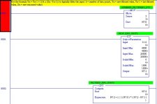
There are three kinds of "filtering" we are talking about here:

1) Electrical signal noise from EMI or RFI - this is best handled by capacitors or signal conditioners or the analog inout channel built in filtering.

2) Filtering out a momentary bump to prevent premature alarms and such. This is best handled with the time delay mentioned above. I usually use some kind of time delay on any alarm for just this reason.

3) Filtering out fluctuations in the transmitter output from a transmitter with a very fast response or a signal that has a lot of inherent ripple - for example a pressure transmitter on the discharge of a reciprocationg air compressor.

The third can be done on most A-B PLCs using a compute block:

cpt_flt.jpg
 
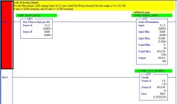
The 5/02 doesn't support CPT, so you have to roll your own with four function math. In this case I'm using a timer to control the frequency of the filtering, and the number of data points is adjustable. I've used this or similar techniques on all kinds of PLC brands and all kinds of analog signals.

Part 1 of 4:

4fnfilt1.jpg
 

Similar Topics

I have been using Islatrol line filters on the machines that i have been building but curious as what brands others may be using.
Replies
4
Views
1,431
Does anyone have a good filter code I can use to allow the data value on the HMI screen to be more readable when the data is noisey (bouncing...
Replies
23
Views
11,087
Hello, I am running a AMCI SD4840 Stepper Motor drive system with Allen Bradley CompactLogix. Every now and then when a 480VAC motor kicks in on...
Replies
1
Views
589
Hello Everyone, I hope we are all well. I have an L36ERM with a 1769-OF8C/a driving a 5HP Power Flex 523 speed reference 4-20 mA. With the...
Replies
6
Views
1,835
Good Morning , We have a new Fortress Stealth Metal Detector. About 30' away we have a machine with motors and solenoids on it , Whenever...
Replies
8
Views
2,193
Back
Top Bottom