Electrician4JC
Member
Hello all. I have a problem trying to read 4-20mA into a Micrologix 1000 Analog PLC. Not sure if my issue is with wiring, or an option within the PLC, or even the PLC itself.
I scoured the message boards and found a wiring schematic for creating 4-20mA using a potentiometer.
One leg of the Pot wired in series to 950ohm resistors.
Wiper of the pot wired in to the IA/2(I+).
Last leg of the pot wired to the 0VDC bus. IA(I-) wired to the 0VDC bus.
24VDC -----(950ohm)---+
|
|
(5k pot)-------- to PLC input IA/2(I+)
|
|
0VDC -----------------+------------ to PLC input IA(I-)
When I check my circuit with a meter, I am able to read 4-20mA fine, but when I connect to the PLC and check my inputs with RsLogix (in online mode), I:0.6 just seems to flipflop between 0 and 1, and doesn't seem to change no matter what direction I rotate the pot knob.
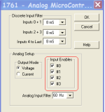
I've checked the IO Configuration>IO Setup>Input Enables and made sure that Input #2 is turned on. So not quite sure what else I can do to read the signal into the PLC.
Any suggestions are appreciated.
Thank you and blessings!
Mark.


