wiring PLC digital outputs to VFD

unsaint32

Member
Join Date
Oct 2012
Location
minneapolis
Posts
365
I am studying this AB 160SSC VFD. I have attached a picture from online manual of this VFD. It shows wiring method IF I used regular PBs and toggle switch. Since terminal 7 is "common," I figured 5, 6, and 8 are V+. Am I correct so far?

My PLC (micrologix1000) output terminals have VAC and output terminals but no COM terminal. So, the only way to wire it is to wire VFD's #7 terminal which is COM to VAC, (and each PLC output terminal to 5, 6, and 8, which doesn't make sense.

help please.

thanks.

ab 160c default input mode.jpg
 
My PLC (micrologix1000) output terminals have VAC and output terminals
What is the model number? If it is only labeled VAC, then I'm guessing it's a 1761-L32AAA? That model has triac outputs (except outputs 0 and 1), and triacs cannot be directly wired to a VFD. You would need to use interposing relays. Relays get turned on by the PLC, and the relays' contacts connect to the VFD.

🍻

-Eric
 
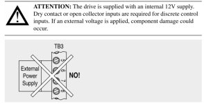
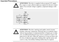
As the manual states,the drive has an internal 12V power supply. You may want to use interposing relay(s). Use your output to fire the relay, use the relay contacts in place of the PBs.

Sorry for the duplicate reply, Eric beat me to it, I'm trying to type with a two year old jumping on me.

Attention.PNG Control Inputs.PNG
 
Last edited:
Using three relays makes sense. But I am going to go home and try wiring the way I had explained in my original posting. I know it doesn't make sense to wire the PLC's output VAC terminal to VFD's COM terminal. But someone at work told me it would work. I will let you know the outcome. Thanks for all your help.
 
Using three relays makes sense. But I am going to go home and try wiring the way I had explained in my original posting. I know it doesn't make sense to wire the PLC's output VAC terminal to VFD's COM terminal. But someone at work told me it would work. I will let you know the outcome. Thanks for all your help.


Try to avoid breathing in the smoke when you do this...
 
The triac outputs of the PLC, are not meant to switch Low voltage DC. Even if it did happen to work, I would not trust it for operation.

If your PLC is AWA or BWA, then your common on the PLC will be VAC/VDC. This is a relay output (dry contact), you just cannot connect anything else to an output going to the same VAC/DC
 
The schematic you're showing above is using a power loop that is internal to the drive. You'll need to use relays off your outputs in order to do this properly. There may be a way to use external power for the drive IO, but I haven't seen a 160 for a little while.

Using three relays makes sense. But I am going to go home and try wiring the way I had explained in my original posting. I know it doesn't make sense to wire the PLC's output VAC terminal to VFD's COM terminal. But someone at work told me it would work. I will let you know the outcome. Thanks for all your help.

I could see this working potentially. Are you sure the VAC terminal doesn't say something like "VAC-VDC"? Basically, if you have a PLC with relay outputs, then yes you'd essentially be using the VFD's internal voltage as a common signal and the contact closure on the internal relays in the PLC to do the same thing as external interposing relays. If it has triac outputs, the results are a bit more unpredictable. Triacs still put out voltage even when they're off. A substantial amount, in fact. And putting DC voltage on triacs designed for AC...I don't know.. Without knowing the exact model Micrologix you're using, nobody can really say.
 
Last edited:
But I am going to go home and try wiring the way I had explained in my original posting.
Wait! First let me take out a fire insurance policy on your home. I could use a few thousand extra this month....

PS: Can I have the old VFD, once you burn out the 12 Volt input circuit?

Don't accept the words of the men who have wired up a thousand. Instead read the warning in the manual.

If your VFD is a Catalog No. 160-DM-SF1 (Analog), or a 160-DM-PS1 (Preset), then it may have a 24V DC Interface Module. In which case you might carefully wire its Input terminals to the PLC Outputs of certain models of the MicroLogix1000. It all depends.

Rockwell 160-SSC Drive Warning.JPG
 
Last edited:
I am studying this AB 160SSC VFD. I have attached a picture from online manual of this VFD. It shows wiring method IF I used regular PBs and toggle switch. Since terminal 7 is "common," I figured 5, 6, and 8 are V+. Am I correct so far?

No. You are not correct, so far. Terminals 5, 6 and 8 are current sinking DC inputs.


My PLC (micrologix1000) output terminals have VAC and output terminals but no COM terminal. So, the only way to wire it is to wire VFD's #7 terminal which is COM to VAC, (and each PLC output terminal to 5, 6, and 8, which doesn't make sense.

It doesn't make sense because it is wrong. Why ask for help if your intention is to simply ignore the advice that you are offered?
 
Still waiting... :confused:
Unsaint was very busy today. First there was the fire department, then the insurance adjuster, then the wife and kids wanting to know where they were going to sleep tonight!
 
Guys I don't think he was necessarily intending to use an external power supply on the drive terminals. I think he was doing something like this


7 VAC
X----------X
OUT0 5
X-----------X


Terminals 7 and 5 are on the drive, VAC and OUT0 on the PLC.

Where the 12 Volt DC Power from the drive would provide the FEED for the outputs themselves, and go back to the drive, closing the loop. If his controller has relay outputs, I'm pretty sure this could work. But if he's using Triac, I couldn't say what would happen, especially on outputs designed for AC voltage only.
 
Sure, you can use relay outputs to connect directly to the drive, but I wouldn't recommend it. In the case of this particular drive, you would suffer from significant voltage drop with the standard 12 VDC power supply if your wiring exceeded a length of 50 feet. Besides, it's just a bad idea to expose this low voltage wiring to the electrical noise that routing it into an I/O panel would likely entail.

You'd only need 1 interposing relay to run the drive forward, and 2 relays if you want forward and reverse operation.
 
Sounded like the OP was just hooking it up temporarily to experiment, but yes, if you were designing something permanent, separate relays are the way to go.
 

Similar Topics

Hi, I'm using an Allen~Bradley PLC, Micrologix 1500, 1764-24AWA Base Unit and the Allen~Bradley 1769-OB32 DC Output Expansion Card. The AC drive...
Replies
16
Views
25,399
Posted this to Reddit with little success, so I figured I would share it here as well. Very new to PLCs, but figured I would give it a shot to...
Replies
0
Views
122
I'm currently working on a PLC setup and could use some advice on the best way to manage my power supply units (PSUs). Here's the configuration...
Replies
3
Views
407
I need one PLC to receive a signal from another PLC. Can I wire the PLC output of one PLC to the input of another PLC? (same voltage of...
Replies
15
Views
3,928
I'm a beginner and not sure what to do. I want to monitor the rotation of a motor. I have a FX3U PLC and a RI58-O/100 encoder available. The...
Replies
2
Views
1,415
Back
Top Bottom