0-10 V DC standard input/output range

Rengas

Member
Join Date
Mar 2013
Location
Birmingham
Posts
88
Hello everyone,
I'm evaluating common analogue standard encountered in PLCs.

Can anyone please post a link or point me in the direction where i can get an explanation to the main advantage of having a 0-10vdc standard input/output voltage range please.

Your contributions deeply appreciated.
thank you.
 
Disadvantages of 0-10Vdc:

A field instrument using a voltage signal output is by nature a 3 or 4 wire device, requiring a 3rd or 4th wire for its power; compared to a 2 wire loop powered 4-20mA field instrument that derives its power from the signal wires.

Current signals are immune to minor resistance changes (rusty terminal screws) in long distance cabling, whereas a voltage signal loses some of its signal over any resistance.

Getting 10V out of milliamp current signals requires a higher burden resistor to convert the current to voltage, which can push the limit of the current driver, as opposed to 5V or 1V

0-10Vdc lacks a live zero which is an indication of a broken or open circuit. 1-5V, or 2-10V does have a live zero.

A current signal can be converted to a voltage with a suitable resistor, but a voltage signal requires a signal conditioner to convert to a current signal.

The 4-20mA current signal can carry the HART protocol for smart communications (setup/diagnostics/multiple variables). 0-10Vdc can't.

0-10Vdc as an output can not drive conventional devices like 2 wire valve positioners which derive the power to operate from the signal line itself.

The nature of intrinsic safety that requires a barrier lends itself to a current signal, less so to a voltage signal.

The corresponding input or output does not take 0-10Vdc


Advantages of 0-10V:

0-10Vdc shows less noise than lower dc ranges, like millivolt signals, because its signal is larger in the signal to noise ratio.

Voltage signals are monitored more easily in troubleshooting situations because the measurement can be made without breaking the circuit, which the requirement to put the meter in series in the circuit, as a 4-20mA current signal requires.

The concept of 'splitting" a voltage signal by paralleling it is more easily understood by Bubba than putting two devices in series for a current signal.

It's the signal that's available for use.
 
Last edited:
It's the signal that's available for use.
I think this is probably considered the main advantage of a 0-10 volt signal: when it is the only one available. Note that Dan's Advantages list is much shorter than the Disadvantages list. 4-20 mA is my preference when I have a choice.
 
Voltage signals are monitored more easily in troubleshooting situations because the measurement can be made without breaking the circuit, which the requirement to put the meter in series in the circuit, as a 4-20mA current signal requires.

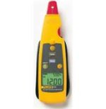
Get yourself one of these. No Need to shut down to break the loop. It is a Fluke 771 milliamp process clamp meter.

fluke 771.jpg
 
Thank you all for replying to my post.
I've been away working and have just got back.
Hence the reason its taken me long to reply.

Many many thanks to you all.
 
i am using 1734-IE4C analog i/p module,for flow,pressure measurement..i dont know the raw values..now i cant connect the instrument and take the min,max of raw values..but i want to put the min,max raw values in SCP ..what would be the range values?
 
What would be the range values?
From the Allen Bradley User Manual 1734-um001_-en-p[1].pdf, paage 104:
(The 1734-IE4C is not given, but should be a 4-channel version of the listed 1734-IE2C, with the same range parameters).

Analog Input Modules
The 1734-IE2C Analog Input Module is a two-channel module that converts an analog input current to a digital value. The module resolution is 16 bits across 0 to 21 mA. The module has two modes.
0…20 mA
4…20 mA (default mode)
Scaling to any 16-bit signed integer (–32,768…+32,767)
Default for 1734-IE2C scalers are +3277 @ 4 mA for low, and +16,383 @ 20 mA for high
Operates in Unipolar mode
 
Last edited:
4-20ma sensor signalling standard

I was asked to evaluate a 4-20 sensor signalling standard as well and aslo asked to ensure my answer explains why 4mA represents the minimum value and not 0mA

This was my answer. Please see if thats ok.

4-20mA signalling standard is
An “analogue” electronic signal is a voltage or current whose magnitude represents some physical measurement or control quantity. An instrument is often classified as being “analogue” simply by virtue of using an analogue signal standard to communicate information, even if the internal construction and design of the instrument may be mostly digital in nature. This is to distinguish such instruments from those making use of no analogue electronic signals at all (e.g. wireless or Fieldbus instruments). It is the modern system used for PLCs because of their insensitivity to electrical noise.

The most popular form of signal transmission used in modern industrial instrumentation system is the 4 to 20 milliamp DC standard. This is an*
analog*signal standard, meaning that the electric current is used to proportionately represent measurements or command signals.*
Typically, a 4 milliamp current value represents 0% of scale, a 20 mA current value represents 100% of scale, and any current value in between 4 and 20 mA represents a commensurate percentage in between 0% and 100%. 4-20mA is superior for long distances, like those encountered in a steel mill, oil refinery or chemical plant that covers, literally, square miles .
 
analogue industrial instrument 0-10vdc a/d channel

Also ive been asked to describe one industrial analogue instrument that would be used with the 0-10V DC A/D channel.

Please check if this answer is ok.

The Electro-Sensors SA420 Signal Conditioner is a complete system which provides an analog signal directly proportional to the speed of a monitored shaft. The 0-10 Vdc outputs can be sent to a chart recorder, digital display, PLC, loop controller, drive speed controller, or any other control or monitoring device. The wide voltage range and wave shape flexibility of the SA420 input circuitry allow it to translate signals from Hall Effect Sensors, proximity switches, magnetic sensors, and a wide variety of other pulse generators, into analog outputs.
 
This is to distinguish such instruments from those making use of no analogue electronic signals at all (e.g. wireless or Fieldbus instruments).
I think it goes back to much earlier times, long before wireless and Fieldbus instruments were invented or were even dreamed about. Originally there were only On/Off devices. When early air-pressure-controlled instrumention became available, there was needed a new term to distinguish from the old On/Off (digital) control methods, thus "analog" (or the older spelling "analogue"), which originally meant "something having analogy to something else." Thus an analog signal was one that represented a proportional amount of some other thing, value or range.
 

Similar Topics

Hello, I have a small programming task that I need help solving. I have to: * Create an analog input (4-20v)and a digital output * The analog...
Replies
45
Views
25,091
HI! i would like to inquire.. is there a -20 to 20mA signal??...
Replies
5
Views
1,699
Hai, any of you can suggest where I can get details of Functional block of S5 plc to convert various type of analog signal to digital? Gireesh
Replies
1
Views
3,198
After some interesting conversation regarding the safety of emergency stops, I saw some posts talking about the safety standard conversation...
Replies
21
Views
418
I have programmed servos from a handful of variety of manufacturers and series. Each time I used a PLC without motion functions. I have not worked...
Replies
9
Views
726
Back
Top Bottom