Continuous Forward/Reverse Motion

mechenix

Member
Join Date
Aug 2013
Location
MD
Posts
9
I'm a complete noob to this...

Basically I have to design a project that can be done in a 2 hour lab session, and I wanted to use it as a chance to introduce PLCs.

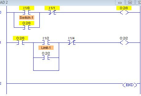
My idea is to implement and program a PLC that can run a motor forward, hit a limit switch, reverse, hit a limit switch and do this continuously, or until it is stopped by the user.

How can this be done, how do the limit switches fit into the basic motor seal-in circuit? What type/model of PLC would be cheap and easy to implement in a classroom setting? I basically need to figure out how to design this in detail, but I don't actually need to build it myself.
 
Student? Teaching assistant? Instructor?

It will also be helpful to us if you will tell us the make/model of the PLC. There are dozens of brands and every single one of them is different.
 
You will need two booleans. One boolean is your running/stopped status. The other is forward/reverse. The user controls the running/stopped status with push buttons or an on/off switch. The limit switches change the state of the forward/reverse boolean.
 
Yes, I'm a student (ME). It's a summer class so we don't have time to actually construct/test the device so I'm just trying to understand fully how this should be done.

As far as the PLC model goes, I have no idea. For this application, I suppose it doesn't need to be too robust, or have a ton of I/O. I just need to pick one that would be relatively cheap and simple to implement, as it is a theoretical application. I feel as though I may be in over my head, because I'm basically teaching myself all this in a 3 week span.
 
You're making this too hard.

Write a boolean statement for running, then convert it to a ladder statement.
running := (start_button or running) and not stop_button

start_button stop_button running
----] [-------+-----]\[----------( )---
|
running |
----] [-------+


direction := (limit_swithc_1 or direction) and not limit_switch_2

Do you see how the running bit and the direction bit use the exact same logic construction? From there try and create your own ladder statement for the direction.

(note that when you use an actual device in the lab the logic might have to be reversed to account for whether any of the switches have normally open or normally closed contacts.)
 
Ahh, thank you, that makes perfect sense.

Now in terms of taking that direction output and connecting it to the motor, I'm guessing that is very dependent on the model/type of PLC I plan on using. It seems that I would need two of those logic statements, 1 for each direction, then I would need to take those outputs and connect them to the motor in opposing fashion. Also, what kind of affects would this have on the motor, will it run smoothly or be a very abrupt change in direction. I have seen timers used to attempt to make the forward reverse transition more smooth and prevent any shorting.

I feel I may need more research on how to physically create this type of system now.
 
I feel I may need more research on how to physically create this type of system now.
Because your example Youtube video used an Allen Bradley MicroLogix PLC (programmed with RSLogix 500 software), I suggest that you get a free 15-day trial copy of the LogixPro 500 Simulator software and write your simple motor control program using that software. The advantage is that you get to use trial-and-error until you find a method that works, without having to buy a MicroLogix PLC to do your testing.

http://www.thelearningpit.com/lp/logixpro.html

http://www.thelearningpit.com/lp/doc/index.html
 
Last edited:
Do not connect your PLC outputs to the motor. The PLC outputs cannot handle the load of a motor. Connect the run forward and run reverse PLC outputs to the coils of relays. Wire the motor to the relay contacts.
 
Do not connect your PLC outputs to the motor.
There is no motor, or PLC either. It is a student theory problem. The best student solution is to use PLC simulator software - cheap, fast, no dirty hands, and no equipment cluttering up the apartment.
I just need to pick one that would be relatively cheap and simple to implement, as it is a theoretical application.
 
just to throw a spanner in the works of your program
it dose not matter for testing BUT
when you swap a motor from forward to reverse it is a good idea to allow a few Milli seconds of delay time.
good practice to avoid the posibiity of bringing both contactors on at once.
I understand - again not needed here - just a thought

Yea I was thinking about that, but since I'm basically designing a lab that future students could do, I figured I'd let them think about this.

I have a couple questions still...

1) Are certain I/O "nodes" designated for certain types of signals. For instance, are I:0-4 only for digital or does it not matter really where I wire certain things up? For reference, I'm designing this lab around the micrologix 1000, might be overkill but it's all hypothetical.

2) I was playing around with the RSLogix demo software, and I couldn't get the "fwd LED" and "rverse LED" to simultaneously turn off and on respectively. The goal of the lab is for a machine to undergo continuous motion. So the slider on the machine would run forward hit a limit switch, reverse, hit the other limit switch, run fwd.... Can this be done with 2 limit switches only, 1 NO and 1 NC, or would I need 4. 1 set to stop the fwd and another set to simultaneously start the reverse circuitry for the motor? (I can post a screenshot of what I had been doing if helpful)

3) I noticed that the micrologix has a 24V DC output, I'm assuming I need to find relays that close when 24V is introduced. Or am I way off here, and the PLC only outputs much less voltage. I tried looking at the user manual but was still confused.

Thanks
 
1) Are certain I/O "nodes" designated for certain types of signals?
Yes, and the two basic types are Digital (On/Off) and Analog (continuous signal over some Min to Max range). Your MicroLogix1000 has mostly Digitial On/Off Inputs and Outputs. However there are about 3 models of the MicroLogix 1000 that have analog I/O: the models that have a "-5A" at the end of the model number. See Appendix A-1 in your MicroLogix 1000 User Manual for a list of the Hardware Specifications of each MicroLogix 1000 model. As almost all beginners, you have failed to state WHICH model you have, and until that is known, all question answers can only be vague and based on guesswork.

2) Can this be done with 2 limit switches only, 1 NO and 1 NC, or would I need 4?
Yes, you will be able to control Forward and Reverse with 2 separate physical limit switches. Each switch can be either N.O. or N.C. (because you can adjust your PLC program logic to work with either switch polarity).

(I can post a screenshot of what I had been doing if helpful)
If you had posted that at first, you would have all these questions answered by now! A picture is worth 1000 words.

3) I noticed that the micrologix has a 24V DC output, I'm assuming I need to find relays that close when 24V is introduced.
Again it depends on WHICH model you have. Some MicroLogix1000s have 24 VDC-only outputs, some have 120 VAC outputs, some have relays that will accept a wide range of voltage inputs. Please post your model number. The model number is what tells the story of what you have. It takes awhile for most beginners to realize that there are thousands of different models of PLCs, just like automobiles, and no one would expect all cars to be alike in every detail. Why would PLCs be an exception? We need different tools for different jobs.
 
Last edited:
Well, I don't actually have the PLC, nor will I ever have it, as this is not actually being built. I just need to do a "detailed design," and I'm not sure which model will do what I want it to. I suppose I just need the PLC power supply, 1 on switch, 1 off switch, and 2 connections for the 2 push button limit switches. I don't even know what kind of input the limit switches provide, I read something that said digital and I'm not sure this model has those types of inputs. So in total, I guess I need 4 inputs and 2 outputs, of what sort, I do not know.

So let's just say I have this model PLC 1761-L20BWB-5A. My idea is that 2 DC outputs will go to 2 Relays that are hooked up to a 12 V DC power supply, one for forward and one for reverse for the DC motor. The limit switches are just there to induce the forward or reverse motion.

Here is the screenshot, obviously I'm clueless. I figured out how to get it to go forward, but obviously once switch I:1/4 is hit the forward motion stops, but I can't figure out the logic for a 3rd rung, that will cause the I:1/4 switch to start the reverse motion.
Capture.jpg
 
So let's just say I have this model PLC 1761-L20BWB-5A.
Okay, done. Now you have selected a MicroLogix 1000 PLC. That means you are restricted to using the Input and Output addresses available for that PLC. The MicroLogix Input addresses start at I:0/0, and Outputs at O:0/0. Slots 1 and 2 are not used (as in your picture).

Here is how I would do your Motor Forward and Reverse program using two limit switches I:0/2 Reverse Limit, and I:0/4 Forward Limit.
I read something that said digital and I'm not sure this model has those types of inputs.
Yes, all PLCs have digital inputs and outputs, but some do not have any analog inputs or outputs.

Mechenix's Fwd-Rev Motor Control Rev 0.jpg
 

Attachments

  • Mechenix's Fwd-Rev Motor Control.ZIP
    5.5 KB · Views: 17
  • MECHENIX'S FWD-REV MOTOR CONTRO.pdf
    24.1 KB · Views: 30
Last edited:

Similar Topics

Hi Guys, I'm new to controls and PLCs and this might have a trivial answer. I have a small project with a PLC and a inverter. The inverter...
Replies
25
Views
3,685
Curios on the thoughts of using Continuous vs Periodic tasks. . The old SLC-500's mostly only had Continuous tasks. . The Compact & Control...
Replies
49
Views
13,845
Can anyone explain to me why Rockwell thinks a Continuous task is better than a Periodic task? That is what it defaults to. It may cause your...
Replies
10
Views
2,905
I've got an SLC500 running a 1746-hstp1 controlling a stepper motor. What's the best way to set the motor to run continuously? I only see Jog...
Replies
10
Views
3,147
We have a cutting machine that we designed in house. It uses an encoder to follow the motion of the product and a cam instruction to cause the...
Replies
20
Views
8,209
Back
Top Bottom