Help: PLC Ramping Continuous vs Discrete

NewEngineer

Member
Join Date
Apr 2023
Location
Singapore
Posts
5
Hi Guys,

I'm new to controls and PLCs and this might have a trivial answer.

I have a small project with a PLC and a inverter. The inverter accepts power (kW) setpoints from our PLC. All through Modbus TCP.

The requirement is when there is a setpoint change from the PLC the inverter must ramp up to the setpoint value ie. not do a step response. The ramp rate is defined as kW per minute.

For example the inverter is switched on and is required to ramp up to 100kW.
Inputs:
Initial Power Output: 0kW
Setpoint: 100kW
Ramp-rate: 20kW/min

This means the inverter must ramp linearly from 0kW to 100kW in 5mins.

From my understanding (please correct me if I've wrong) is the PLC outputs signals every scan cycle (outputs are updated every scan). This means the PLC would be sending a new setpoint at a repeated time interval (fastest would be the fixed scan time) in order to ramp up to the setpoint.

The initial thinking was sending time interval setpoint points to the inverter. eg., add 0.33kW (20kW/60) to the current power output at every 1s trigger (This is an example, time interval can be reduced but problem still exists with smaller steps). The attached PNG graph explains the problem more clearly.

Is it possible to produce a linear signal on the inverter for this application without the steps, if so how?

Thanks in advance!
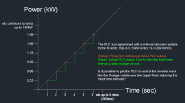
RampRate.png
 
Last edited:
Welcome to the PLCTalk forum community !

Making a smooth linear analog command or signal with a digital source is a fundamental challenge of all digital electronics. The smaller the digital increments, the smoother the signal appears.

If your inverter can take an analog signal like a 4-20 mA or 0-10v as its command instead of a Modbus/TCP transaction, then you can divide the ramp into very small time intervals as fast as a few milliseconds, making it very smooth.

Your analog modules might even have a built-in ramp feature that lowers those increment times even further.

But with Modbus/TCP as the mechanism to send the data to the inverter, you're not going to get a transaction every PLC scan cycle. You're just going to have to decide how fast to send those Modbus value changes, and that's likely going to be in the tens or hundreds of milliseconds.

If the inverter has a ramp feature built-in, of course that's the best approach.
 
The flip side of this is of course the ability of the inverter to produce an infinitely variable output. If you're currently writing a setpoint via modbus, what's the resolution of that value?

I.e. if it's an integer with no implied decimal points, then 0-100 = 0-100kW and you have 1 kW steps anyway.

If it's 0-1000 and that equates to 0-100.0kW then you have a resolution of 0.1kW.

If it's a float then we can't glean much from that.

I would start on the inverter end and figure out what its capabilities are based on manual and/or datasheet, and then see if you can match that with the PLC.

As Ken said, if it's got its own built in ramp function that helps
 
What's the inverter you're using? I can imagine that anything with that power output would have the ability to ramp to reduce or avoid stress in the whole energy transmission/distribution.
 
Welcome to the forum and welcome to the world or real time.

Most PLCs implement a timed interrupt of some sort by which you can guarentee a fixed rate code execution e.g. every 20ms. By making use of this feature you can produce a rate of change limiter that increments/decremments your setpoint by an amount proportional to your rate limit every scan.

Example:

Code:
Const: Max_P = 100.0 \\ Max power in KW
Const: 100_PC = 10000.0 \\ Output that represents 100%
IN: SetP \\ Power Setpoint
IN: KWPM \\ Rate limit KW/M
IN: Cycle_T \\ Execution cycle time in S
INOUT: Output \\ Power output 0 - 100_PC
Local: INC \\ calculated increment per cycle

INC = ((KWPM/Max_P) * 100_PC) / (60/Cycle_T) \\ Increment per cycle

IF (Output > Set_P)
     Output = Output - INC
     IF (Output < 0)
          Output = 0
     ENDIF
ENDIF

IF (Output < Set_P)
     Output = Output + INC
     IF (Output > Set_P)
          Output = Set_P
     ENDIF
ENDIF

Nick
 
Thank you all for the input!

From what I gathered, when continuous signal outputs (eg., the ramp) are required the way it's accomplished is by using fast interval setpoint outputs to smooth the ramp (making the steps as small as possible). Saying this means decreasing the time interval of each setpoint increment. Due to the nature of electronic outputs the signal is never completely smooth.

@Ken Roach, Saffa, Cardosocea - The inverter does in fact have a built in ramp function. I was trying to implement this on a controller, however it looks like the built-in function would be a possible better solution.

@Manglemender
The PLC does have a timed interrupt, just checked the fastest time is 1ms. I could potentially run the ramp program in there. Thank you for the suggestion, I will give it a go.
 
Thank you all for the input!

@Manglemender
The PLC does have a timed interrupt, just checked the fastest time is 1ms. I could potentially run the ramp program in there. Thank you for the suggestion, I will give it a go.

One thing to bear in mind is that there is no point running your ramp routine faster than the I/O or comms will update. 10ms would be plenty fast enough in all probability.

Nick
 
One thing to bear in mind is that there is no point running your ramp routine faster than the I/O or comms will update. 10ms would be plenty fast enough in all probability.

Nick

That's good point -
When a PLC jumps out of the main cycle to execute a interrupt, during the interrupt does the PLC update the outputs (writes to the inverter) before going back to the main program or does the update of outputs only happen after the main program finishes executing? If it's the latter then the interrupt is limited by the main program scan.

For example if I have 60ms for the main program cycle and 20ms cyclic interrupt does the PLC write twice to the inverter within the 60ms or does it update the output only at the end of the 60ms cycle (neglect the time spent in the interrupt)?
 
I would not program an 'increment per cycle'. This will sum up a small error at each cycle, which will be greater the smaller the increment and can be quite significant after 5 minutes.

Instead I would use a timer for the duration of the 5 minutes for the change, and calculate the fraction of the full setpoint based on the fraction of the time expired. You will then get precisely 100 % of the setpoint when the timer reaches 5 minutes.
 
You have not said what PLC, so it will depend on that.
Most only update outputs at the end of scan, however, some can do immidiate update refresh, some have asnc I/O that could update peripherals many times during scan.
 
That's good point -
When a PLC jumps out of the main cycle to execute a interrupt, during the interrupt does the PLC update the outputs (writes to the inverter) before going back to the main program or does the update of outputs only happen after the main program finishes executing? If it's the latter then the interrupt is limited by the main program scan.

That depends...

traditionally, most PLCs only update the I/O at the beginning/end of the main program cycle. At the beginning of a cycle the actual inputs are read into a input process image. The main program executes using the process image inputs and sets any out puts in the output process image. At the end of the main program scan the ouput process image is transferred to the actual outputs.

Some PLCs update I/O acyclically from the main program cycle (Rockwell I think?) and this can catch people out. In some PLC languages, for example Siemens PLCs, you can read and write directly to the I/O and this is often used in timed interrupt routines. Read direct from Inputs, execute interrupt code, write directly to outputs.

So, the short answer is: it deponds on what PLC you use and how you write the program.

Nick
 
@JesperMP makes a very valid point.

To make that work you would need to recalutate the ramp time for every change in setpoint based on the rate limit given.
 
What is the data format of the variable that is sent to the VFD ?
INT, DINT, REAL, .. ?
If it is an INT, then the max value is 32767, and you will only see a change in the value approximately every 9 mseconds. 300000 ms / 32767 = 9.15 ms. (*)
I think that you dont have to worry about achieving a smoother transition of the setpoint value than what you can achieve with the regular PLC cycle. Even if the variable is a DINT or REAL, in the real world I dont think it is worth trying to get a smoother transition. Every 10 ms is still much smoother than every 1 second, by a factor 100.

*: This assumes that the value is scaled to 100% = 32767. If 100% is less than 32767, for example 10000 = 100.0 %, then the change in the value will be even less frequent.
*: Or 10000 = 100.00 kW
 
Last edited:
For example if I have 60ms for the main program cycle and 20ms cyclic interrupt does the PLC write twice to the inverter within the 60ms or does it update the output only at the end of the 60ms cycle (neglect the time spent in the interrupt)?


I don't have much to offer to solve the problem beyond what the other experts have said. PLCs operate at discrete times. You can at best approximate a continuous linear-in-time signal via discrete Modbus messages, and the approximation to continuous is limited by how quickly the Modbus messages can be sent; the I/O update time does not matter if Modbus is used to transfer the signal.

What I would like to say instead is that you are asking excellent questions. You are not assuming the PLC can do what you want, but are rather investigating what the PLC's limitations tell you about how close it can get to what you want.


TR;DR (Too Ridiculous; Don't Read)


The closest to continuous signal I can think of would be an analog output signal from the PLC to an analog input on the inverter, but with some intermediate filter (RC circuitry?) to modify the signal that the inverter sees. The PLC would send a discrete ramping (i.e. stepping) analog voltage that leads (i.e. is slightly greater than) the inverter signal voltage, so the inverter signal voltage would be continuously "climbing" toward the current step PLC signal. The slower the filter and the greater the lead, the more steadily the inverter signal would climb.

I did say it was ridiculous. Look for a ramp function in the inverter. It will be discrete, but at a much faster than can be achieved from the discrete PLC.
 
Siemens PLCs, you can read and write directly to the I/O and this is often used in timed interrupt routines. Read direct from Inputs, execute interrupt code, write directly to outputs.

I haven't tried this in TIA portal, but do the PIW/PQW "shortcuts" work there as well?

Or link the card refresh to the OB that uses those signals... though this requires quite a bit more thought.
 

Similar Topics

I have a network with 4 PLCs PLC1 is controllogix and PLCs 2-4 are compactlogix and they all need to communicate. The current way I have this...
Replies
8
Views
264
So to start off: I have no experience with PLC's, but I'm good at figuring stuff out, but I need some help to know if my PLC is just dead in the...
Replies
2
Views
117
Hi guys, I have no experience when working with AllenBradley PLC, but I hope someone could clarify the result of multiplication shown in the...
Replies
14
Views
2,201
To quickly test a plc output which is wired to a relay do I dob a cable between the output and 24vdc+ source I.e something with 24vdc+ live such...
Replies
6
Views
696
Back
Top Bottom