Manually dobbing in plc outputs help please!

D.bull

Member
Join Date
Oct 2023
Location
Uk
Posts
3
To quickly test a plc output which is wired to a relay do I dob a cable between the output and 24vdc+ source I.e something with 24vdc+ live such as a terminal. I know it’s all wired correctly but I’m not a plc engineer and just want to test and prove by bringing in the out put the relay changes state. So is it one end of cable to 24vdc+ terminal and other dobbed on output? I thought I’ve heard people say it’s on a 0v leg but just want to know !
 
If not how do you recommend I dob in the output to get the relay to change state with just a piece of cable
 
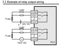
It depends what sort of output it is, and/or how it's wired. It could be an NPN output, in which case you'd use 0V. It could be a PNP output, in which case you'd use 24VDC. It could be a relay output, in which case you'd use whatever voltage is connected to the other side of the relay.

If you're not sure, put the wire down and find out. If it's a relay output with 110VAC on one side of it and you put 0VDC on the other, you could find yourself having a Very Bad Day
 
To quickly test a plc output which is wired to a relay do I dob a cable between the output and 24vdc+ source I.e something with 24vdc+ live such as a terminal. I know it’s all wired correctly but I’m not a plc engineer and just want to test and prove by bringing in the out put the relay changes state. So is it one end of cable to 24vdc+ terminal and other dobbed on output? I thought I’ve heard people say it’s on a 0v leg but just want to know !


If you know that the PLC is all wired correctly, then you shouldn't need to do anything aside from forcing the outputs on and checking that the attached relays change states.
 
If not how do you recommend I dob in the output to get the relay to change state with just a piece of cable

If you need to connect the relays to your output module, you should find the exact part number of the module and search online for a user manual that will specify the appropriate wiring.
 
Normally you wire 24v to the common pin on the plc output terminals, relay to the desired output pin & the other end of ther relay to 0v.
Just be aware some relay outputs may have individual commons some have only one common & others may have them split into banks i.e. 2 or 4 outputs per common.

PLC wiring.png
 

Similar Topics

Hi there, I am trying to determine the input, output, and config assembly and entering it into a beckhoff plc, and couldn''t get proper active...
Replies
22
Views
7,370
Hello everyone‚ Fairly new to PLC prog I seek your advise concerning what is said in my thread title; I program using workbench components; I...
Replies
1
Views
1,255
We have a customer that requires a CISCO network switches by government regulation. We are using a IE-4000-8GT4G-E industrial network switch. I...
Replies
37
Views
18,701
Dear Sirs, I have several Siemens MasterDrives (of dubious parentage) and I'm not sure if they are operational or not. I have an old laptop...
Replies
9
Views
2,809
I need to increase a servo motor's ability to hold a load in place when work is being performed against it. This project is in a metal forming...
Replies
0
Views
1,400
Back
Top Bottom