PID Tuning and Importance

Join Date
Oct 2003
Location
Mansoura
Posts
46
Dear all,

I want help from all. I need to know exactly How to tune PID controller block and what is the exact values for P, I , D.

also I want to know some more about the Importance and function of PID as I know it represents 85 % of all controller.

Thanks in advance.
 
Before calculating the PID gains, you have a system model and a desired response.

You first must have a model of your system. A simple motor in position mode has a model of G/(s*(tau*s+1)). G is the gain in velocity per volt, tau is the time constant and s is the Laplace operator. From here the models get much more complicated.

Next you must specify the desired response. Chosing a slow response will result in lower gains and a faster response will have higher gains. You must specify the response by chosing desired poles locations in the s plane. If you want to have a nice critically damped response then all the poles must be on the negative real axis in the s plane. For faster response they should be placed as far to the left , more negative, as possible. There is a practical limit to how far the poles can be moved to the left as the controller can't generate an infinite control signal even though it is theoretically possible to do so.

Once you know the model of your system and where you want the poles to be then you can use a technique called pole placement. See my temperature example.

Calculating PID Gains on a Temperature Control System.. In this example I used the data from Ron Beaufort's 'Hot Rod' system from last summer. I place the all 3 poles on the negative real axis so they all have a time constant of .6 minutes. This is just an example. The equations for calculating PID gains change each time the system model changes.

Most people can't follow all of this so they just guess at the PID gains until they get a response they can live with.
 
Peter, I am glad that you ended up by telling m_abd_el_khalik
the way it is actually done in the field!

Most people can't follow all of this so they just guess at the PID gains until they get a response they can live with.
 
It's sad.

Lancie1 said:
Peter, I am glad that you ended up by telling m_abd_el_khalik
the way it is actually done in the field!

m_abd_el_khalik wants to calculate 'exact value for P,I,D' so I told him. I expected the post to be too much information. If m_abd_el_khalik really understands his question, then maybe he will understand the answer. If not, oh well. I don't expect anyone to understand the post or the web page, but maybe some one will. I feel there are about 10 people that frequent this site that do or could understand this topic with a few days of training.

As for how it is really done in the field. I find this sad. Some people have the 'knack' and can tune systems with little help from tuning tools. Unfortunately, many systems are poory tuned. This results in a loss in productivity, quality or an increase production costs. Now think about the millions of dollars wasted because of ignorance of proper PID tuning.

I pointed that to calculate the gains, one must have a model of the plant. This is very educational as one begins to realize what is really happening from a plant designer's standpoint. Plant designers can then see where the plant can be made more linear or have fewer poles and shorter time constants. OK, so you aren't plant designers. Still you should be able to get the best perfomance possible from your PID system.

Here is a trick that I use. Each scan I calculate the error between the SP and PV. I then square this error and add it to a running sum after a change is set point. The process industry calls the ISE ( integrated squared error ). Once you have the ability to calculate the ISE one can adjust a gain and try the change is SP again. If the ISE goes down then you have made a change in the PID gains that improve the response. If the ISE goes up then the change you made was not for the better and old gains should be restored. This makes a game out of tuning. The only problem is that it can take minutes for larger temperature systems to cycle between two temperatures. In this case it is faster to have a good mathematical model so one can tune and run the simulation quickly.

Here is an example of how winners tune PIDs in the field.
Tomato Processing with PID Termperature Control

Now, are you a winner or loser?
 
PID tuning

I find this emperical method of PID tuning from the Micrologix 1500 manual is quite good. From 1762-rm001e-en-p section 19-23.

http://www.ab.com/manuals/cp/1762-rm001e-en-p.pdf

Another way to do it;

1.Turn off the I and D compnents
2.Set the P component until the process oscillates at its natural period
3.Set the loop update time to 1/10 of the natural period
4.Set the P component to about 1/2 that required for oscillation
5.Adjust P until the process is steady but with a steady state error
6.increase the I component until the steady state error is within limits
7. If external influences cause instability then introduce some D term until the process is stable.

Test using a step test.

Process overshoots - Increase D or reduce I

Process oscillates reduce P

Process under shoots but reaches SP then reduce D

Steady state error - increase I

Response too slow - increase P or I

Bear in mind that changing one parameter will influence the others and depends on the PID equation you are using.

Make only SMALL changes.

Use a graphical recording device such as a chart recorder or TrendX in RSLogix to follow your process and analyse your adjustments

If it will not control then go back and start again, don't persist with adjustments if you loose control of your process.


For slow response systems a D term is not usually necessary so turn it off if you don't need it.


If you have the choice use a purpose built PID controller with auto tuning and fuzzy logic. PID control in PLCs is difficult at best and can be a nightmare.

.
 
Originally posted by JohnW:
PID control in PLCs is difficult at best and can be a nightmare.
I am about to do some PLC based PID control, and am certainly not interested in any nightmares.
Can you elaborate about the problems you have experienced ?
 
"the exact values for P, I , D."

Peter may disagree, but in my experience their are no exact values for the tuning constants of a loop, even if transport and control capacities and resistances remain constant. And, of course, in most applications they DO NOT remain constant.

Mustapha, the PID equation is not a mathematical model of a physical phenomenon like f=ma for uniform acceleration or Q=VA for fluid flow rate. Rather, it is a mathematical representation of a controller's output in response to deviations between the actual and desired process variable.

For most PID loops there are a variety of tuning constant values that will control the process to a satisfactory level. For most processes there are an infinite number of tuning constant values that will create an absolute mess in the process. And there are some processes for which no set of tuning constant values will produce satisfactory results.

Beyond that, the definition of "satisfactory" has been the subject of many a long, hot debate.

There are hundreds of articles and books software packages and self-tuning algorithms devoted to determining reasonable tuning constants. And, when all is said and done, for many processes you start with these pre-determined values and then hope you have a guru like Peter around to tweak the results until you get "satisfactory" control.
 
Last edited:
Hi Jesper,

The main problems fall in to two areas - PLC related and process related

PLC related, a sound knowledge of the PLC program and the PID equasion is required, this can be particularly difficult with the AB PLC5 with 2 different PID equasion options. You need to study the PID equasion and understand how changes of each component will affect the overall output value. Also understand how the PLC evaluates the PID equasion and how often. I have seen programs where the programmed PID update time was different from the actual update time of the PID block and the process data because of timing errors i.e setting the PID update time to 1S but having the PID block update every scan (say 20mS) so the PID block was evaluating a equasion that should update every 1S at 20mS intervals. Having a PID block update quicker than a BTW instruction can access data is another problem.

Process related, an inherently unstable process will be more difficult to tune than a stable one, also the presence of unkown external influences can affect the tuning. It is essential to ensure that the system is working at optimum performance before starting tuning, i.e no faulty control valves or sensors. Sometimes a process will control OK until some event occurs outside of the control loop, then the tuning either has to allow for this or the progam has to change the PID parameters and the system is re-tuned to handle this event. I have a system where I know that an event will occur that gives a spurious sensor reading but I still need control, so I reduce the P component of the loop until the event has passed. For instance the movement of a steam heating plate will result in a slug of condensate reaching a sensor and giving a spurious drop in temperature so I know the plate is going to move and cut the P component by 90% unit the plate is stationary again.

The faster your system works the harder tuning can be, I used to tune analog gunnery systems on warships and to tune the gun mounting to follow a sine wave control input and getting 49 tons of gun mounting to follow at an error of less than 3' of arc was not easy.
 
Yep, sometime you are out of luck.

Tom Jenkins said:
"the exact values for P, I , D."

Peter may disagree, but in my experience their are no exact values for the tuning constants of a loop, even if transport and control capacities and resistances remain constant. And, of course, in most applications they DO NOT remain constant.

If the plant remains the same and the desired response stays the same the gains will remain the same. Each time my Mathcad works recalculates it comes up with the same answer as long as the plant model, sensor model and desired response stay the same. NOW TELL ME WHY IT WOULDN'T. It is just hard to keep the plant the same.

Sometimes model of the plant will change, but that is no excuse for giving up. The next step is to understand how the plant changes. Sometime a table of gains can be made so as the load changes, the gains can be changed. On presses with jack rams, it is common to change gains on-the-fly. There is one set of gains while the fill valve is open and another set of gains while the fill valve is closed. There is even another set of gains when controlling pressure or force instead of position.

Remember ROI? A professional should know when good enough okay and when to used advanced techiniques until the point if diminishing returns is reached.

JohnW. Your example is a step in the right direction. It is better than guessing. I think the way you change the gains based on condition is good also. Tuning as system that responds faster is harder only if the sample time of the controller is not fast enough. I do a lot of motion control. We can update as fast as every 250 micron seconds although there are few physical system that require this speed.

Another step would be to by PID tuning software from a company like expertune or bestune. Finally, one can get someone who really knows what he is doing.

JesperMP, the biggest fear I have is DEAD TIME. Dead time is the result if poorly designed systems using the wrong control components like a proportional valve with over lapped spools instead of a servo quality valve. Or a pump that requires 100 milliseconds to respond to any output. Dead time is the delay to a control signal. In some process the dead time can be very long, on the order of minutes. This may happen in a mixing situation where a material is mixed in another but the sampling is done down stream where one can't tell if the mixture is right until the new mixture reaches the sampling point. This is where PLCs PID fail. You can't adequately control these systems with JUST a PID. The big DCS systems have the ability to model the plant and predict the response ( Smith Predictor ).

I teach classes aimed at giving customers a better understanding of hydraulic motion control and our controllers. One of the sections is tuning. We still use the integrated squared error approach to PID tuning because we have made it simple to do so and it always works. However, I stress that the PID gains are NOT the most important gains. Feedwards are the most important gains. If the feed forwards are tuned up correctly then you actually have the inverse model of the plant. A controller can estimate the control output to within 5% if they are set up properly. The PID is just there to compensate for load changes and non-linearities. We have a procedure that allows one to calculate the velocity and acceleration feedforwards pretty accurately.
 
Tom,

I see that you think like I do when it comes down to the Real World versus the Theoretical World. After 30 years trying to make the real world conform to mathematical ideas of what it SHOULD be like, I have given up trying to change it. I now accept it for what it is: pure chaos. There is no way to accurately describe most real-world processes using a mathematical model. Oh, sure, Peter, the math will work, but the problem is that we normal humans cannot usually figure out which equations to use at any given moment in time. At best, we get PART of what is going on, and make ASSUMptions for the unknown factors. (You all know what ASSUME makes out of U and ME.)

A good example is a project that I worked on, 5 years ago now, but I have not forgot the lessons learned. It was a PLC-controlled blender that mixed precipitator dust with water. The only reason to mix in the water was to make the dust less dusty so that it could be handled easily and hauled to the landfill without blowing around. If too dry, it fogged up when dumped. If too wet, it became sticky mud which rapidly changed to concrete.

The day we were to deliver the blender to the customer, I finally got to see it tested. I took one look at how it was working and could tell immediately that it would never do the job, no matter how it was tuned or adjusted. My boss, on being informed of my opinion, spent the next 2 hours in front of a blackboard, going through the mathematical equations that describe how dust and water mix, and showing me exactly why the blender WOULD work, if only the right dust-to-water ratio was achieved. As for me, all I could say was, "that's equations on your blackboard, but the blender will be up at Raggoteux in the real world." He was not convinced in the least way, but $60,000 and two months later, the customer jerked the blender out and declared that he was not paying one dime to our company. The dust was coming out of the blender in one of two states: two dusty or it set up like concrete and had to be chipped out by hand.

I am sure that all my boss's equations were mathematically correct and were applied correctly. It is all the unknown factors (changing density of the dust, varying temperature of the dust and water, vibration of the blender platform so that weighing the dust was not accurate, and so on) in the real world that we did not know about up front and so could not adjust for, that spoiled the project.

During the two months that I spent on-site, trying to modify the PLC program and make the blender work, the plant foreman asked me how I would do the job if I had a chance to re-do it starting from scratch. I told him, "I would buy an enclosed dump truck, and build an enclosed fill chute, and haul the dust as it is." So he did.
 
Not a chance.

Lancie1 said:
I am sure that all my boss's equations were mathematically correct and were applied correctly. It is all the unknown factors (changing density of the dust, varying temperature of the dust and water, vibration of the blender platform so that weighing the dust was not accurate, and so on) in the real world that we did not know about up front and so could not adjust for, that spoiled the project.


I bet the mixture had to be just right with little tolerence for error, EVER!!!. A since a PID only works when there is or has been error then a PID would certainly fail in your example no matter how good the calculations are. I think the biggest error was to assume perfect mixing. From my experience with cooking, I don't see how any fluid can be added to a powder without it clumping. There just isn't any way of mixing the first drop of fluid in the powder evenly.

The problem probably wasn't in the math. The problem was in the model that assumed perfect mixing.
 
Peter... You never cease to amaze me...and damm you at the same time...reading your posts brings back memories of what i studied and have gladly put all that information in the back of my mind, and then you go and tease my curiosity again, and it all comes back...argh!!

John W, thanks for your layman explanation also...

m_abd_el_khalik, and Jesper you might also look into the Ziegler Nichols Method for tuning PID...a search on the web will provide a whole heap of info on thei method.

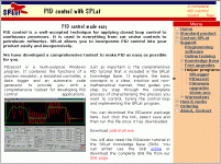
Also i found this free PID download software from SPLAT...So far it looks good.

This will keep me amused for a few hours...

Heres the link

Free PID Simulation Software from SPLAT

pid.gif
 
I forgot to add... a number of the newer PLC's these days come with an Auto tune function, i certainly know that the Omron CJ and CS series PLCs have this capability....
 
oooh..... neat..........

The log files from SPlat can be imported into Excel. Then one can use the LINEST function to calculate the coefficients for a model. From the model and a desired response, one can calculate the gains.

I just got through logging the response to some open loop square waves. From the graphs I can see that the system is a second order lag system. This is like having two RC circuits back to back or cascaded. If so then the equation for the model is simply.

y(n+1) = A1*y(n)+A0*y(n-1)+B1*x(n)

The trick would be to calculate the coefficients A1,A0, and B1 unsigning the Excel's LINEST equation ( I prefer Mathcad ). Then the above difference equation needs to be converted to a transfer function in the s domain using the equations in the .ppt file in the post above. Finally one can use the link below to calculate the gains.

Calc PID gains for second order lag system

Maybe this will put a few more wrinkles in the gray matter.
 

Similar Topics

Hello, I am attempting to tune a PID loop on a process. The process involves a valve with electronic actuator that has quite a high deadband...
Replies
10
Views
2,191
so i have 4 25gpm wells feeding a 1000gal tank (T-1), with an additional 15gpm from a decant tank for 3hrs every 12hrs. P1 and P2 both controlled...
Replies
154
Views
35,919
Hi everyone, yet another PID problem. I'm hoping I understand enough of the process I'm controlling that my request for help is reasonable. If a...
Replies
113
Views
28,104
A few months ago, I started to look into PID controllers and the tuning of first order processes. This has, partly thanks to you, resulted in a...
Replies
162
Views
62,391
I haven't had to tune a PID loop in a very long time. It's actually a PI loop for a pulse width modulation s.v. What was the name of that tuning...
Replies
16
Views
4,114
Back
Top Bottom