help with PID control

Mopar5

Member
Join Date
Feb 2014
Location
NL
Posts
9
I'm working on a PID ladder logic program to control a small process trainer as a college project. 2 valves in a split range setup control hot and cold water going to a heat exchanger which heats or cools water circulating in a tank. A RTD in the tank measures the temperature as the variable.

Basically. I'm having some trouble with logic though as I don't have a lot of experience with it.


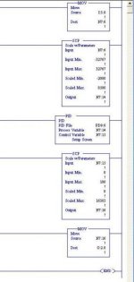
Here's what I have so far. I'm using a Allen Bradley 1500. With an RTD card and analog I/O cards. The RTD is I:3.0. According to the RTD the ouput range is -32767 to 32767 and I have that scaled to -200 to 800 degrees celcius which is its temp range even though I'll only be using a small part of that range. That's outputted to the pid function as the variable, then the output of the pid controller is changed from a 0 to 100 scale to 0 to 16383 for a 4-20 ma signal to the current-to-air transducer that tees to the valves, which is the O:2.0 you see.


Does this make sense to anybody? What else do I need for this to work? I still need to make another loop to control the level in the tank but I'd like to get one thing working at a time.
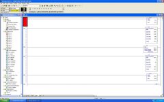

ladder.jpg
 
For best help, post your program its .RSS file zip it first.

Tell us what type of RTD you are using.

The PV (process variable) for the PID instruction should be scaled to 0-16383 (Scaled for PID) this can be configured in the analog card setup.
 
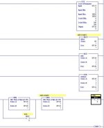
This is the file. It might not be clear because not everything is labeled but basically the first couple of LADs are for basic manual control of things on the trainer. LAD 6 is the 4 total RTD units on the trainer that are scaled.

7 and 9 are what I was working on. 7 is what I had shown above. When I tried to have the RTD scaled to the -200 to 850 degrees of temperature into the PID block I would get an error when I tried to download. (36H I think) If I made it 0 to 100 it worked again.

LAD 9 is my attempt to control tank level with a rosemont transmitter and a solenoid valve. I'm very new at this, so I wasn't sure how to control a on/off device like a solenoid from an analog input. I figured if controller output is less than 50 it could be off, and on if above 50? I'm sure that's not the correct way to do it though.
 
For your PID in lad 7...
Change your analog input card channel 0 ( I:3.0) to "Scaled for PID" data format (0-16383)

Change your analog output cards channel 0 data format to "Scaled for PID"

Move I:3.0 to N7:14 with a "MOV" instruction.

Set the Setpoint Max (SMax) to 850
Set the Setpoint Min (SMin) to -200 ( In the PID configuration) This works without error I just tried it.

Move N7:15 to O:2.0 ( the PID instruction outputs 0-16383 to N7:15)

As far as the tank level control I would not use a PID for this. I would use a couple of "GRT" ( greater then) instructions with a deadband. Say off at 45 on at 55.
 
As far as the tank level control I would not use a PID for this. I would use a couple of "GRT" ( greater then) instructions with a deadband. Say off at 45 on at 55.
Yes, you could but I don't think that is the point. If I were going to college I would want to learn how to use a PID instead of just getting the project to work.

If I were an instructor I would chose tank level control for a starter project. To get a passing grade one would have to write the differential equations for the tank.

On linkedin I got into a heat argument with people that told the student to tweak gains until it work. One doesn't go to college to do something a 1000 monkeys could do if given enough time.
 
Mickey, I understand what you mean but I'm not 100% sure how to implement it.

I scale the transmitter to 0-100 and have a set point of 0-100 of level. I could use a simple "less than" instruction? If set point is less than level than the solenoid will open and drain the tank. The problem is I have no dead band that way, I could add +5 and -5 to each side of the set point?
 
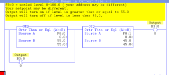
Thanks a lot for the help so far! So does this make sense, or do I have set point and transmitter inputs backwards? This is if I have set point as 60 for example.

rsz_1122.jpg
 
I think your source A in both GEQ should be N7:18 (I think Mickey also typed this as well). Your diagram shows the second GEQ testing N7:19 >= N7:21 which would always be true (test 60 >= 55).
 
Still working on this. I tried the level control using Mickey's logic and it works, but I had to make the GEQ's into LEQ's since the solenoid is closed when energized. Also it clicks on and off like crazy when the level is on either end of the set point, so I need to add something for it to only energize when it has to change states. When it opens at 55, for it stay open until it goes down to 45 for example. What would I use for that? Thanks again.
 
I think you should revert to using GEQ's as in Mickey's logic ending in the B3:0.0. Then use normally closed B3:0.0 out to O:x.x if your valve is closed on energizing.
His logic is sound if you copy it exactly (with the source in both GEQ's = N7:18 as in your diagrams).
The thing that's not very obvious (but very important!) is that the second GEQ is the low limit and the 1st GEQ is the high limit.
 

Similar Topics

Hello all, I have an issue with a PID block in RsLogix 5000. The parameters are P: 3.25 I: 0.11 D: 0.01 The Set Point is 71 psi This loop...
Replies
63
Views
14,809
So were commissioning all the PID loops I had programmed to work with the new wonderware HMI system that was installed. Got all but 1 tuned pretty...
Replies
3
Views
2,351
Allen Bradley PLC 5 What operations wants to do is as the Oil Flow rate (0-3000 m3/d) increases more chemical is injected into the flow line...
Replies
8
Views
2,492
Hi All, I have been asked to modify our contact tank pumping station controls. Currently pump speeds are manually entered (as %) by operators...
Replies
2
Views
2,224
Good Day, I have been programming for a while and a complete newbie in using a PID Control block. Now i am studying 📚 it using PC...
Replies
12
Views
4,574
Back
Top Bottom