OT: Drawing # Scheme

Tim Ganz

Member
Join Date
Dec 2010
Location
Dallas, Texas
Posts
689
What is a good way to make up a drawing # scheme? I see many draws that have for example 6818-1.

The will be internal end user drawings as we are not an OEM or integrator but a production plant.

Just looking for ideas.
 
When I was an end user I started all of my drawings with the machine number
1~10 informational ( network layout, notes, BOM...)
11~20 power distribution (480, 240,....)
21~30 motors
31~40 safety
41~50 local plc
51~60 RIO rack 1
61~70 RIO rack 2

I now use
A# info
B# power distribution
C# Motors
D# safety
E# PLC
F# ....


This way I keep my systems as close as possible from one to the next.
 
cover sheet - title page
index
480 volt
240 volt
120 vac / 24 vdc
power controls
building layout of machine area
machine layout - views
sensor placement - balloon numbers and detail the inputs
enclosure layout
enclosure panel
plc layout
plc I/o

you get the picture.

in the end, you must what is best for you.
regards,
james
 
These will be internal end-user drawings, as we are not an OEM or integrator, but a production plant.
For plant internal drawings, the best drawing numbering system is simple but still allows the users to easily find one drawing in a file of thousands. Some plants divide the facility into physical sections with a prefix number or letter for each section, but others divide the drawings by type - civil, mechanical, electrical, piping, and so on. There is not necessarily a best way, but merely the best way for your plant based on its past practice and what can be made to work for all parties.

One good simple way that I have seen is simply to start the first drawing ever made for the plant at Drawing # "100-X", where the X represents the type (C, M, E, etc), and continue with the next higher number "101-X" for each new drawing. This will work, but usually is so simple that the plant suits think somehting is wrong and it has got to be made more complicated than that. One government facility that I worked at started with this system in 1915 and worked up to around drawing # 65000-X (or somewhere in there), then started over again at "N100" for New Drawing Set.
 
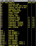
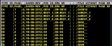
Drawing type Table; Position Table; Drawing List Source Table

Filename is "Drawing type ID&Position ID&Page number"
CAEE system extends page number to Filename so there are own file for every pages.

In Positon table, 1'st column is design postion what you like and Customer Position
repaly it in wiews on PDF/CSV/DXF/DWG files.

DRW TYPES.jpg POSITIONS.jpg DRW LIST.jpg
 
Last edited:
In my career I have worked for and with dozens of different companies, an every single one had a different drawing number system. And every single one was convinced theirs was the best and most logical system.

I have reached a few conclusions:

- Keep it simple. The systems that try to convey a lot of part configuration or function information in the drawing number are more work than they are worth.

- In general, non-specific part numbers seem to be most efficient. The savants that can remember lots of part numbers can remember lots of any numbers! If you want to use a prefix or suffix for broad categories, such as 20 for PLC stuff and 10 for hydraulic stuff that can be useful (But it can also lead to endless time sucking brain numbing arguments between guys that should be doing something useful instead.) You can get carried away easily - a separate part number sequence for analog inputs and analog outputs, for example, adds little to information retrieval and less to company profitability.

- Document it. Every engineer, purchasing agent, draftsman, and field service tech should have a sheet explaining the system. If it wont fit on an 8-1/2 x 11 (or less) in 12 point font it is too complicated.

- Be Consistent. Establish a system and rigidly enforce it. Anyone with a bright idea for improvement needs to be slapped down, even if it is a better idea. The company should have better things to do than renumber drawings every three years.

- Remember the point. Drawing numbers are simply a means to aid information retrieval. They are not intended to provide an intellectually satisfying hobby for the engineering department rain men.
 
Last edited:
Internal drawings - I just name them. Eg, drawings for widgit stamping machine #1 are named WidgitStampingMach#1. Next we use E for Electrical, M for mechanical, etc. So the first page of the electrical drawing set is "WidgitStampingMach#1-E01.

External drawings are numbered with the the job number, followed by the Exx or Mxx page numbers.
 

Similar Topics

Looking for any information or ideas on drawing sets that have multiple control panels on them. Where I currently work we typically only have 1...
Replies
3
Views
2,487
Just curious what the 'standard' is where you are. I assume 11 x 17 (or A3 for ISO people) is standard, but I could be wrong. My shop was using...
Replies
31
Views
13,917
Just wondering for those of you who work on process machines, do you typically make your drawings follow the ISA designations or do you have...
Replies
7
Views
2,229
I have a pdf schematic drawing of a control panel that I made a few changes to. I would like to document the changes on the drawing but I don't...
Replies
12
Views
4,732
Hello ! I need help to understand these arrows on this solenoid this solenoid is activated electrically by 110 VAC and it is being used to...
Replies
7
Views
1,914
Back
Top Bottom