traffic light - don't burn me yet!!!

westikle

Member
Join Date
Jun 2014
Location
NC
Posts
26
Hi all,

Yes this is the "good ol' traffic light" problem. I've done a lot of searching on this site, and i don't want THE answer, because i know it can be done a million different ways. What i'm looking for is some guidance in getting it to work a specific way, to better help me understand the logic behind it. This may be a long read so bare with me.

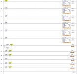
I'm three weeks into an intro to PLC class, and i have a worthless instructor. He has showed us normally open, normally closed, and how to create a seal in. Now we've already hit the traffic light problem and i'm stuck. If you go by the book, you start out with just three lights on three different timers; red, amber, green. Then you move to six lights. Now, the book shows you how to add a fourth timer (for the other green) to make all six work. Below is a pic of the ladder, and the .rls file.
LadderRungsTB.jpg

View attachment trafficbook.rsl.zip

Notice the first timer is for the red light. I've seen on this forum that most solutions involve timers for the amber, green, and green delay. While that makes good sense and all, it's not how the book shows, and i'm trying to stay on the path. It took me a while to figure how the fourth timer comes into play, but i've watched it enough now to make sense of it.

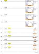
And this is where my problem comes in. The book says you can add two more timers to get a two second time period where both lights are red. Seems this forum calls it a green delay. Now i could start over from scratch and have six timers, and three different times, but i don't think the book is suggesting this. Keep in mind this is supposed to be a cascading type timer thingy. My instructor won't answer my questions without suggesting i draw a timeline and a bunch of ****, and basically start all over. I'm trying to build on what i already have. So i've added a fifth timer and have the green delay working on one side...
LadderRungsOneDelay.jpg

View attachment trafficbookwithonedelay.rsl.zip

I felt good to at least get one side working without any help. But i do need help getting the other delay to work. Every time i throw a sixth timer in there, everything goes crazy. I would really appreciate some direction from here. Also, i'm only using enable and done bits. i'm hoping this will help me get a better grasp of the logic. If you made it this far, i really appreciate your time. And i hope i've made this not just another traffic light post, although i'm sure someone will chime in and say otherwise.

Thanks
Wes
 
My instructor won't answer my questions without suggesting i draw a timeline and a bunch of ****,...
You can get by without the ****, but you should draw the timing diagram. A timing diagram will make it obvious as to where you need the new timers to be inserted into the logic. If you don't know where you are going, what the goal is, then you will most likely wander around in the muck for a long time before your accidently stumble upon the solution.

This is for the usual student solution: The truth is that the best construction is FOUR timers for the basic 2-directional 6-lamp traffic light (Green & Yellow timers for each direction). The Red lights are simply the Green and Yellow Times added together for the opposing direction, so you really never need Red light timers. Then to add the overlapping red (delayed green) option, 2 additional timers are needed.

About the time you do all this, you realize the whole thing, including the overlapping reds, could be easily be done with only 1 timer by using comparison instructions!

I will see if I can duplicate your LogixPro program and figure out where to add the last timer.

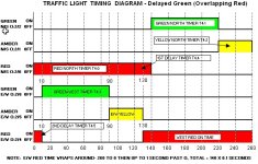
Yes, here is the timing diagram that you needed. Now look and tell ME where the 2nd Delay timer needs to be added! I drew this using the Microsoft Excel spreadsheet program, copy available if you want it.

Traffic Light Timing Diagram w Delay- Wes.jpg
 
Last edited:
Thank you for the reply. What i meant to say was, my instructor won't help me further along with what i already have. He's basically saying "just start over and do it my way." I understand the usual student solution, it's plastered all over this forum. I agree it makes more sense and is also cleaner. But going by the book, this is the direction it puts you in, so i know it is possible. Once I get past this, i'll explore other solutions. Thanks again!

Wes

edit: also, that first timer designated for the red north... I realize that's not the ideal way to go about this problem, but it came from the first scenario where they wanted three lights on three timers. Everything thing has built from there.
 
Last edited:
and i have a worthless instructor
It seems like everybody who comes here looking for help with a school assignment has a worthless instructor. Personally, I think not. A good instructor challenges you to think for yourself. You won't always have someone looking over your shoulder pointing out where you've gone astray.

My instructor won't answer my questions without suggesting i draw a timeline and a bunch of ****, and basically start all over. I'm trying to build on what i already have.
Sometimes, when your initial approach doesn't lend itself to an efficient solution of additional requirements you have to start over. His suggestion that you draw up a timing chart is excellent. You should have done it before you started to write any logic. If you haven't done it yet, I suggest you do it before you try to patch your existing logic.

Once you have the timing worked out, enable the traffic light sequence and monitor the .EN and .DN bits to see how they behave. With that information you should be able to properly apply those bits to the actual outputs.
 
Wes,

Looking at the timing diagram, I see that you have some errors in your program caused by adding the delay times. For example, you have the West Red light triggered when T4:0/DN goes on. The timing diagram shows that with the Overlapping Reds, that will no longer work. Instead, use the West Yellow Done to trigger West Red.

Oops, you don't have a West Yellow timer! Now you are in deep doo-doo! To keep your current construction (not recommended), you can readjust the timer presets. You could set T4:0 to 130, and the First Delay timer from 20 to 10, making the total ON time for North Red still 140. Now your original logic for STARTING West Red will work (now it must be sealed in to stay ON after T4:0 goes OFF), but you have to add a series XIO T5:5/DN to turn off West Red.

Also you will need to add the 2nd Delay timer T3:5 to be triggered by T4:0/EN and then using T4:5/DN to start T3:3 (after only 1 second).
 
Last edited:
Steve, i appreciate your response. While i may have came across as a whiney student (i'm sure that happens a lot on here, i've read some myself,) i do mean what i said about the instructor. maybe "worthless" is a little harsh, but i wouldn't hesitate to say useless. he didn't know he was teaching the class until i walked into his office fifteen minutes prior to ask what book i needed. he obviously doesn't want to be there, and has offered nothing in terms of guidance or anything else that goes along with teaching. if you wanna talk oklahoma state football, however, that's a whole different story. his one good bit of advice has been to make a timing chart. of course, he didn't mention that until we had all been scratching our heads over this for a week. i understand it may not be his fault there was some confusion with the faculty, and i'll give him that benefit of the doubt. but i'm a paying student and i have certain expectations from a college institution. Also, my initial approach is all i have to work with, being that the book is my only source of direction and information. that's why i'm on this forum.

Lancie, thanks, i'll check that out when i get to class today. I'll check back with any more questions that may arise.

Wes
 
I'll check back with any more questions that may arise.
You will find that after adding the 2nd E/W Delay Timer, you will need to redo the logic for both red lights as follows:

North Red now turned ON by series combination of XIC T4:0/EN and XIO T4:4/DN.
West Red now turned ON by parallel combination of XIO T4:5/DN and XIC T4:0/DN.
 
So i did some messing around.

Lancie, I understand that the red lights need to overlap, and it looks good on a timing chart, but i'm not sure how it works in logic. Either way i added a sixth timer. I didn't have to change any times like you had suggested. Everything is running smooth (almost, i'll get to that.) The switches for the red lights don't match up quite like you said, and i still only have one for west red. That makes me scratch my head a little. But there is one little problem. I don't know if you have logixpro and can run the simulation to see what i'm talking about. If not maybe someone else can chime in, or i'll let you know when you give me your thoughts on what i have so far.

Thanks
Wes

btw i just now saw the image you attached above. it didn't appear earlier. apparently i'm attaching images wrong.
 
Last edited:
geez, forgot to attach my own files....


View attachment traffic with flicker.rsl.zip

attachment.php


yeah i'm not doing it right...

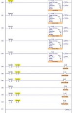
trafficflicker.jpg
 
Do it like the attached LogixPro program (as I said before). This is not the best way, but simply continues what you were doing with the 4 timers and 2 Overlapping Red timers. This version will run at a 100% scan rate (for awhile anyway).

Once you see it running, do not quit, but go back and study the timing diagram until you understand how to read it. If you continue in this field, you will need to be able to figure out the timing issues in many different programs.

Your errors are still in your Red lights. Rungs 006 and 009 are both incorrect. You sort of swapped the logic for some reason.
 
Last edited:
Can you tell me what is wrong with my ladder diagram in more detail? From what i can tell, it runs very smoothly except for the split second the north red light flickers when the west green comes on. I've been studying the way you did it and honestly don't have a grasp on it yet. But i think knowing what is wrong with mine may also help. I know it's a lot to ask from someone i don't know and isn't getting paid to help me, but i do really appreciate the time you've taken to help me. anyone can ask for solutions to a problem but i'm really trying to understand what i'm doing. what do you mean rungs six and nine are sort of swapped? thank you again. i'm waiting for that light bulb in my head to switch on.

Wes
 
Can you tell me what is wrong with my ladder diagram in more detail?
Yes, if I knew which of your 2 or 3 versions you are talking about. The program that I posted in Post #10 is your version from Post #1, except with the errors corrected so that it actually works, and with proper symbols and comments added. (I bet you did not recognize your own logic!)

Now your next 2 programs in Post #9 are different animals where you switched a bunch of stuff around, so I will have to study it to find the errors. If you keep making wild guesses and then asking for suggestions, it will take a long time to finish! First decide on which version you want to keep (none of them are very efficient).
 
Last edited:
Why are you using .EN in conjuction with .DN? It looks like you're programming a SLC so there should be a .TT flag available on the timer.

That said, if you're allowed to completely deviate from how the book says to do it, I'd do it with a single timer for the entire sequence. Then just using LIM, GRT, and LES instructions comparing the .ACC flag on the timer to ranges you come up with to determine when in the cycle each light turns on and off. That gives you the maximum expandability and flexibility. Drawing the timing chart would be a huge help as well. That way you know where to set your limits.
 
Can you tell me what is wrong with my ladder diagram in more detail?
Here is what is wrong in detail, for each rung where there is a mistake, based on your Post 9 Version 4 of your program (which is different from your first version).

Rung 000: The Red North timer should reset and restart when the North Yellow Timer T4:2 is Done, not when the Green West Delay is Done as you have it. T4:1 needs to have a Preset time of 120 + 10 delay = 130. This is to allow your program to work even while not having a timer for West Yellow! If you had a West Yellow timer, then you could set T4:1 at 120, and your Green North Delay timer to 20 as instructed. The way it is, T4:4 must be set for 20-10 or 10. So your "20" delay is split between T4:0 and T4:4. The result is the same, but the details become confused if you don't know what you are doing. Study the timing diagram to see that I am correct.

Rung 003: The Green West Delay must start at the same time as Red North T4:1, so use T4:1/EN to start and run T4:5. The problem with using T4:2/DN Yellow North is that T4:2 gets reset when T4:0 is reset at the end of the cycle, so T4:5 will start then stop as you have it now. This is probably what caused the "blinking" that you mentioned.

Rung 006: You do not need the T4:5/EN rung branch. The Red North lights are not depdendent on the T4:5 time in any way. Look at the timing diagram. Red North starts at Time 0 for T4:0 and stays on until T4:0 is Done. Delete the T4:5 parallel branch on this rung.

Rung 007: The Green North lights must go ON only AFTER the Green North Delay timer is Done. You have O:2/2 going ON as soon as T4:0 is Enabled. That logic is incorrect. Also, your Green North lights go OFF as soon as T4:0 is Done, which is also incorrect. The Green North Lights must wait until T4:0 is Done AND also until the Green North Delay timer T4:4 is Done to go ON, then go OFF when the Green North timer T4:1 goes from Not Done to Done. Otherwise, your Green North Delay is worthless. Rung 007 should look like this:
 
| Green North Green North Green North |
| Delay Done Done Lights |
| T4:4/DN T4:1/DN O:2/2 |
|------| |-----------|/|-------------( )-------|
| |


Rung 008: Your Yellow North will go on at Time 0 + 1 scan when T4:2 is Enabled. That will work, but it would be best to turn Yellow North ON 1 PLC scan earlier (when Red North T4:1 is Done). This prevents a short 1-scan delay between Green North Done and Yellow North On. In the real world, this 1-scan delay is so short that the actual bulb in the green light would not have time to go off before the Yellow light came on, but in the LogixPro graphic setup, the car drivers can detect that 1-scan period when NO lights are ON, causing crashes!

Rung 009: The Red West lights Output logic has a severe error. It must turn ON at two different times, due to the fact that Red West must "wrap around" on the timing diagram from Time 260 back through 0 and up to Time 10, before turning off. To keep it ON through the T4:0 reset at the end-of-cycle, use a parallel branch with T4:5/DN as I said before and as shown below:
|   Green West Delay   Red West Lights | 
| T4:5/DN O:2/4 |
|--+-----|/|--------+--------( )-------|
| | | |
| | T4:0/DN | |
| +-----| |--------+ |
| |


Make the above changes to your Post 9 version 4 program, and it will work.
 
Last edited:

Similar Topics

I am a complete newbie to this stuff and wanted to try this out and was looking for any information on how I can complete this by Wednesday...
Replies
19
Views
12,742
Hey Folks I've done some browsing along the forum for some help in a matter. It would seem the question has been asked many times but it just...
Replies
41
Views
16,851
I'm looking for a simple, cost-effective way to control traffic lights from a central location. The lights are actually mounted on signs next to...
Replies
2
Views
1,867
Hey guys, I'm fairly new to PLC and RSLogix5000, as I am currently a student. I am doing a traffic light project, which is only running off of...
Replies
8
Views
1,960
Hi all, I am having a problem programming a single traffic light, one red, one green, and one yellow light. I am not a student needing home work...
Replies
12
Views
3,412
Back
Top Bottom