PLC Help traffic light controller

I documented my progress on my website here. You may find some useful information when you start planning to do the layout.


https://www.nepaview.com/model-train-plc-project.html

Thanks I highly appreciate that. I will check it out soon. Oh Ummm I didn't give up. I actually got the delay working. I know the program I created isn't the best and turns out that apparently what I created is like what you would see in some college book or something like that.

Its working the way I want it to and have no hiccups. It even changes the side that was flashing yellow during the night time to a solid green when 6am hits. So that is a plus. So soon I will be designing my train signal program.

Again I really appreciate everyone's help you all rock.
 
Would love to see your final code; PDF is probably best for posting.

I assume the JSR goes to the flashing routine at night? Btw, instead of the B3:0/0 and B3:0/1 kabuki dance for nighttime, consider the LIM instruction: the single rung [LIM RTC 23 RTC:0.HR 5 OTE B3:0/0] or similar should duplicate your Start/Stop pattern.

I still like my post #10 (here), which is really just an alternate form of @parky's simple approach in post #8 (here). It should be trivial to add the nighttime flasher, and not too hard to implement that yellow-flashing-to-green morning transition.
 
d'Oh!

It finally sunk in that this is on a sixty second cycle, so it needs no timers at all, everything can be run off RTC:0.SEC and @parky's approach.

So that is 7 rungs: one for each light; one rung for night or day. Even the yellow light flashing can be driven by RTC:0.SEC/1. I.e. not RTC:0/0, which is always 0, and time resolution for any event is limited to at least two whole seconds.
 
I suspect this brought something between a wry smile and a hearty :ROFLMAO: to several besides me.

... Thank you in Advance and sorry I tend to overexplain things.

No, thank you for cogently explaining your problem. It is much much much easier to filter out too much information than to guess at what has not been provided.

Would that all OPs would do the same; go read a few other more "typical" threads and you'll see what I mean.
 
Implementation using RTC instead of TON/TOF timers.

RSS and other files are on Github at this link.

Caveats/details


  • Limited to one-minute sequencing cycle
  • Limited to two-second resolution of any events, by MicroLogix RTC resolution.
  • Includes
    • Daytime operations with green-yellow-red sequences
      • Greens on for 24s
      • Yellows on for 6s
      • Reds on for 32s, with 2s overlap
    • Nighttime operations with flashing yellow for one way.
      • 0.25Hz, 50% duty cycle
      • If nighttime operation needs a flashing red instead of solid
        • Add [XIC/XIO RTC:0.SEC/1] to lower branch of Rung 0003
        • Add [XIO Nighttime] at the beginning Rung 0005
traffic_light_rtc.png
 
Last edited:
Would love to see your final code; PDF is probably best for posting.

I assume the JSR goes to the flashing routine at night? Btw, instead of the B3:0/0 and B3:0/1 kabuki dance for nighttime, consider the LIM instruction: the single rung [LIM RTC 23 RTC:0.HR 5 OTE B3:0/0] or similar should duplicate your Start/Stop pattern.

I still like my post #10 (here), which is really just an alternate form of @parky's simple approach in post #8 (here). It should be trivial to add the nighttime flasher, and not too hard to implement that yellow-flashing-to-green morning transition.

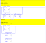
here is my final code. I tried doing all the LIM instructions but for some reason it turned everything into a mess. I'm certain it was something I did but couldn't figure it out. So for now this is the program and the PLC has been sitting over on my other desk running all day with no hiccups.
 
The LIM instruction is worth knowing.


In fact, if you figure it out, your code will not start up in daytime mode if you put it into run mode, or have a power failure, after midnight and before 6am, when it should be in nighttime mode.
 
Last edited:
The LIM instruction is worth knowing.


In fact, if you figure it out, your code will not start up in daytime mode if you put it into run mode, or have a power failure, after midnight and before 6am, when it should be in nighttime mode.

Hmmm that is a good point. I didn't think about that. I will try playing with that again at some time. Thank you again.
 
LIM behavior depends on the relative parameter values, either
[Low Lim] <= [High Lim]
OR
[High Lim] < [Low Lim]
In the image below, the branch on the same rung as each LIM instruction will have the same result as that LIM instruction.
xxx.png
 
This is to point out "duplicate destructive bits." It's working as written but it's not a good practice. Your LAD2 daytime routine and LAD3 nighttime routine have the same outputs duplicated. It works here because of the way the program scans in this PLC. The full program scans, then the physical outputs are updated to match the data table.

In the daytime, LAD3 doesn't execute, so the output data table doesn't update to off for the two lights. At night, the daytime code turns off the two bits, but later in the program scan when LAD3 executes, the bits are turned on in the data table (when the flash is true.) Then the physical outputs are updated to on.

Some PLCs like CompactLogix and ControlLogix update I/O asynchronous to the program scan. On these, the code as written would have the two outputs chattering at night when flashing on. Some output updates would happen between the points in the program where daytime code turned them off then nighttime turned them on. Other I/O updates would occur between the nighttime turn on rung and daytime turn off rungs.

It's common to have a separate I/O routine and use single bits or bits of an integer in the logic and map to the physical inputs and outputs in a single location. In your example, you could have a daytime bit OR a nighttime bit OTE the physical output. An advantage of this is more easily moving physical outputs to accommodate changes at only a single point instead of potentially many places throughout the program.

The separate I/O routine can help with program flow on asynchronous I/O systems because the virtual input bits will not change state until the next I/O routine scan (unless code changes the bits), which can allow logic to not need mid-scan changes considered.

This doesn't necessarily need changed in your program, I'm just pointing it out for learning. The program isn't bad, but any program can usually be improved. I go back through my work all the time and clean things up and make better. I don't have any program I would say is done. If I look for things to make better, I'll find things. I do suggest LIM of the RTC hour for your daytime / nighttime selection so it works with power on at any time.
 
I took into consideration about the timing if I unplugged the PLC or started the PLC up with the enable button I have. I do want to try the limits portion and will eventually try creating a program that uses that, especially after I get more experienced with limits.

I also didn't like that I had the yellow and red in the same rung so I put them in separate rungs.

I also cleaned up all the extra XIO/DN bits on the lights and switched to XIC/TT bits. Looks cleaner IMO

Now about the power failure or the switching of the enabling button. Funny thing is I originally had it functioning that after a power loss or the button change it would still go back. I used Less than or Equal comparisons and that made it work originally but because I wiped out the program at one point I lost how I did it. Well I finally remembered how I did it. I'm not going to explain how I did it but here is a PDF attached showing how I did it.
 
Last edited:
#1: heed @5618's comment: duplicate OTEs is a Bad Thing; you are getting away with it to be sure, but just because there is no one else moored in this bay for the night is no reason to accept that your anchor is dragging. Perhaps the simplest would be to move all of the daytime logic from Program File LAD 2 to a new Program File LAD 4, and simply call (JSR) EITHER one OR the other from LAD 2, but never both i.e. call LAD 4 (daytime logic) when NIGHT_TIME is 0, or call LAD 3 (nighttime logic) when NIGHT_TIME is 1

#2: Add comments: describe the process (e.g. "Determine if mode is daytime or nighttime based on hour-of-day") not the bits and instructions; the reader can look at the code to see what is happening with the PLC internals.

#3: Rung 0004, [XIC T4:0/EN TON T4:3 1.0 15 0], is unnecessary: it starts on the same scan as [RED_1 T4:0] TON timer and is done 5s earlier, so

  • [XIC T4:3/DN] on Rung 0010 can be replaced by [GEQ T4:0.ACC 25]
  • [XIC T4:3/TT] on Rung 0011 can be replaced by [LES T4:0.ACC 25]
#4: Rungs 0012-0014

  • 0012: BST XIC RED_1=O:2/5 LEQ RTC:0.HR 23 NXB XIC NIGHT_TIME_BIT=B3:0 BND BST XIO NIGHT_TIME_STOP=B3:0/1 NXB XIC NIGHT_TIME_START=B3:0/3 BND OTE NIGHT_TIME_BIT=B3:0/0
  • 0013: GEQ RTC:0.HR 6 OTE NIGHT_TIME_STOP=B3:0/1
  • 0014: EQU RTC:0.HR 23 OTE NIGHT_TIME_START=B3:0/3
First of all, I want to compliment you on a classic use of the Start/Stop pattern in Rung 0012, to ensure a clean transition from daytime to nighttime operations.

But after that, oh dear, where to begin ....

  • LEQ RTC:0.HR 23 is always TRUE, so it can be eliminated
  • XIO NIGHT_TIME_STOP=B3:0/1 on Rung 0013 is the only use of NIGHT_TIME_STOP, and is same as LES RTC:0.HR 6
    • So changing the GEQ on Rung 0013 to LES,
    • and ORing it with the EQU on Rung 0014
      • to write NIGHT_TIME_START
    • eliminates NIGHT_TIME_STOP entirely,
      • along with Rung 0013
      • and the XIO NIGHT_TIME_STOP=B3:0/1 on Rung 0012
  • For that matter, that ORed logic on Rung 0014 could simply be moved to the Stop element of the Start/Stop pattern on Rung 0012, eliminating Rung 0014 as well, and leaving only Rung 0012
    • BST XIC RED_1=O:2/5 NXB XIC NIGHT_TIME_BIT=B3:0 BND BST LES RTC:0.HR 6 NXB EQU RTC:0.HR 23 BND OTE NIGHT_TIME_BIT=B3:0/0
  • OR, using the LIM instruction, with [Low Limit] > [High Limit] i.e. reversed, to match "nighttime" hours 0-5 and 23:
    • BST XIC RED_1=O:2/5 NXB XIC NIGHT_TIME_BIT=B3:0 BND LIM 23 RTC:0.HR 5 OTE NIGHT_TIME_BIT=B3:0/0
#5: Flashing is simpler than two timers; LAD 3 need be but one rung:

  • XIC S:4/12 BST OTE RED_1=O2:5 NXB OTE YELLOW_3=O:2/12 BND
And I don't see any reason to put those OTE on separate rungs; the branched output is fine.

#6: If you do insist on doing this with sequential TONs, then at least put them in the order they run (RED, GREEN_2_DELAY, GREEN_1, YELLOW, GREEN_1_DELAY; GREEN_2 is unnecessary and should be removed), so it's easier to read.
 
Last edited:
Traffic lights are a fun known operation project. Many ways to do them. Single timer, compair, sequencer, limits, and on and on.
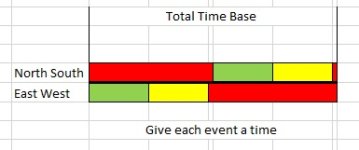
My best advice would be to draw out your timeline and go from there. After one method, try another. I have even spacing for yellow and green. Keep in mind first scan startup should be red both directions and have fun.
Check out the attached pic, plug in your times and write your own logic.


Edit
Where is my attachment.lol

Edit 2 thanks DBB

Red Light.jpg
 
Last edited:
three tries for a quarter!


Also note you can go back and edit previous posts within 1h or so, including edits to add an attachment.
 
#1: heed @5618's comment: duplicate OTEs is a Bad Thing; you are getting away with it to be sure, but just because there is no one else moored in this bay for the night is no reason to accept that your anchor is dragging. Perhaps the simplest would be to move all of the daytime logic from Program File LAD 2 to a new Program File LAD 4, and simply call (JSR) EITHER one OR the other from LAD 2, but never both i.e. call LAD 4 (daytime logic) when NIGHT_TIME is 0, or call LAD 3 (nighttime logic) when NIGHT_TIME is 1

#2: Add comments: describe the process (e.g. "Determine if mode is daytime or nighttime based on hour-of-day") not the bits and instructions; the reader can look at the code to see what is happening with the PLC internals.

#3: Rung 0004, [XIC T4:0/EN TON T4:3 1.0 15 0], is unnecessary: it starts on the same scan as [RED_1 T4:0] TON timer and is done 5s earlier, so

  • [XIC T4:3/DN] on Rung 0010 can be replaced by [GEQ T4:0.ACC 25]
  • [XIC T4:3/TT] on Rung 0011 can be replaced by [LES T4:0.ACC 25]
#4: Rungs 0012-0014

  • 0012: BST XIC RED_1=O:2/5 LEQ RTC:0.HR 23 NXB XIC NIGHT_TIME_BIT=B3:0 BND BST XIO NIGHT_TIME_STOP=B3:0/1 NXB XIC NIGHT_TIME_START=B3:0/3 BND OTE NIGHT_TIME_BIT=B3:0/0
  • 0013: GEQ RTC:0.HR 6 OTE NIGHT_TIME_STOP=B3:0/1
  • 0014: EQU RTC:0.HR 23 OTE NIGHT_TIME_START=B3:0/3
First of all, I want to compliment you on a classic use of the Start/Stop pattern in Rung 0012, to ensure a clean transition from daytime to nighttime operations.

But after that, oh dear, where to begin ....

  • LEQ RTC:0.HR 23 is always TRUE, so it can be eliminated
  • XIO NIGHT_TIME_STOP=B3:0/1 on Rung 0013 is the only use of NIGHT_TIME_STOP, and is same as LES RTC:0.HR 6
    • So changing the GEQ on Rung 0013 to LES,
    • and ORing it with the EQU on Rung 0014
      • to write NIGHT_TIME_START
    • eliminates NIGHT_TIME_STOP entirely,
      • along with Rung 0013
      • and the XIO NIGHT_TIME_STOP=B3:0/1 on Rung 0012
  • For that matter, that ORed logic on Rung 0014 could simply be moved to the Stop element of the Start/Stop pattern on Rung 0012, eliminating Rung 0014 as well, and leaving only Rung 0012
    • BST XIC RED_1=O:2/5 NXB XIC NIGHT_TIME_BIT=B3:0 BND BST LES RTC:0.HR 6 NXB EQU RTC:0.HR 23 BND OTE NIGHT_TIME_BIT=B3:0/0
  • OR, using the LIM instruction, with [Low Limit] > [High Limit] i.e. reversed, to match "nighttime" hours 0-5 and 23:
    • BST XIC RED_1=O:2/5 NXB XIC NIGHT_TIME_BIT=B3:0 BND LIM 23 RTC:0.HR 5 OTE NIGHT_TIME_BIT=B3:0/0
#5: Flashing is simpler than two timers; LAD 3 need be but one rung:

  • XIC S:4/12 BST OTE RED_1=O2:5 NXB OTE YELLOW_3=O:2/12 BND
And I don't see any reason to put those OTE on separate rungs; the branched output is fine.

#6: If you do insist on doing this with sequential TONs, then at least put them in the order they run (RED, GREEN_2_DELAY, GREEN_1, YELLOW, GREEN_1_DELAY; GREEN_2 is unnecessary and should be removed), so it's easier to read.

Noob Question. What do you mean by BST. I'm kind of lost at what your saying. Rungs 10 and 12 I did change that with the GEQ and the LES respectively and like that. Much cleaner. I can agree to cleanup rungs 12 through 14 but the statement BST is completely loosing me. Not to mention adding the Less and GEQ now leaves my GREEN_2 on in night time but that may change cleaning up the night time stuff. I just didn't know what BST meant.
 
Last edited:

Similar Topics

hello everyone i was thinking about starting on a new project on my RSLogix 500, i was going to be doing a traffic project! however, i am a little...
Replies
3
Views
1,805
I am trying to simplify my program to not use the GEQ and LES functions. Can I substitute timers for this?
Replies
8
Views
5,093
I have a network with 4 PLCs PLC1 is controllogix and PLCs 2-4 are compactlogix and they all need to communicate. The current way I have this...
Replies
8
Views
268
So to start off: I have no experience with PLC's, but I'm good at figuring stuff out, but I need some help to know if my PLC is just dead in the...
Replies
2
Views
118
Back
Top Bottom