PLC Help traffic light controller

Geae_Liska

Member
Join Date
Oct 2021
Location
Michigan
Posts
17
Hey Folks I've done some browsing along the forum for some help in a matter. It would seem the question has been asked many times but it just seems like the answers aren't particularly gonna help me. I'm fairly new to the PLC realm of things but feel like I've got a grasp well I hope.

Anyways to make it simple I got an Allen Bradley Micrologix 1100. I'm a traffic light enthusiast and someday when I buy a house this thing will run a traffic light garden with a railroad crossing. I've designed a traffic light controller on my own with a time comparison to switch to flashing red on one side and yellow on the other. So when the time hits it works flawlessly.

The only thing I'm struggling with is the darn gone delayed green. Modern traffic lights hold each way of traffic for a few seconds at all red then change one to green.

If anyone could give me some guidance I where I could get this delayed green working. I myself am going to keep playing around with it and see if I can get something and will periodically keep up to date in here.

Thank you in Advance and sorry I tend to overexplain things.

I have some links showing my current program. All bit not the subroutine for the flashing at night sequence.

Image #1
Image #2
Image #3
 
I took a quick look at your post, its a bit hard to follow since you don't have any comments. Another thing I noticed is you don't have a block occupancy detection bit for the railroad crossing.


I am using a Micrologix 1400 PLC to control a model railroad layout as a learning tool. here is a snip of the code showing how some of the signals are controlled by the block detects. There are conditions for the signals at switches to read the switch position (signal can only be green if the block ahead is clear and if the switch is turned towards that track)


Video demo as well


https://youtu.be/Nuu90Mz7Taw

The railroad crossing isn't done yet. I don't even have a crossing signal to make this work yet. I will eventually get that working. For right now I'm working on the traffic signal part. That is for cars that is.

Eventually when I do the program for the train crossing when I push a button it will latch, turn on the crossing signal lights, gate will lower after about 5 seconds of the lights coming on. After about 3-5 minutes the gate will come up and shut off the lights on the train crossing signal and return the traffic lights back to regular operation. I would like to even do a preemption cycle as well but I feel that is going way further then what I know on PLCs.

Someday I plan on getting another micrologix controller and building a model train setup and using it to control crossings, traffic lights, and lighting for the model.

Right now just working on the setup for my future backyard project.
 
Here is a two way traffic light sequence done in Mitsubishi (easy to convert into RSL), although it's not quite what you want by the use of a sequence variable it is easy to get the steps you want.
I do suggest you use this method it is easy to follow rather than cascading timers & bits & if you want to change the sequence it is easy to add extra steps hence the steps are in slots of 10 so if another is required you have 9 more per original step.

That is pretty interesting. I see its structured logic. Never attempted to use that but I think I can get it. The only thing is I see redamber. I'm assuming this is turning on the yellow when there is still a red light before the green. Similar to what is used in the UK. I don't plan on using that method of light stages. However, it would give me my delayed green.

I'm still playing with my program. I have an idea to get it to delay the green but will try that later today.

If anyone still has an idea with my current program as well I'm all ears.
 
Try the download section... there are a couple of traffic light examples that should help you and first thing before you start programming, put names to all your inputs and outputs then comments as you write the program

http://www.plcs.net/downloads/index...j7&direction=0&order=&directory=Allen_Bradley

I will take a look at the downloads. Thank you I just have to figure out .rsl files.

This is a hobby thing so yes no comments or names but mind you I did have to wipe the program out recently and like I stated in the original message this is a work in progress. I've been adding names and what not as I'm working on the program. I legit just rewrote the program when I sent the photos. When I'm done it will have all the names and what not.
 
Last edited:
That's correct, it is using a 3 light system, the best thing you can do is write out the sequence of events and number them in multiples of say 10 (this gives you the option of adding extra steps should you need them).
for example this would be a pick & place robot:
0 Start at normal position i.e. pick cylinder up, fwd/rev cylinder back, wait for part.
10 part in position, send down pick cylinder.
20 clamp part
30 wait delay for clamp to energise
40 pick cylinder up
50 fwd/rev cylinder forward
60 pick cylinder down
70 release part
80 pick cylinder up
90 fwd/rev cylinder back.
go back to 0

You can drive the outputs with compares for example there are two stages where the pick cylinder travels up & down
so if seq. is 10 or 60 then energise pick down
40 or 80 then pick cylinder up
the clamp will be on between 20 & 60 so this you just compare if >= 20 AND <=60.
 
Well glad to report that with my program I managed to get at least one of the reds and green lights to delay by 3 seconds during the change. Now just working on the second one.
 
Have you looked at the TOF instruction? It is purpose-made for just such a task.

TOF can be difficult to wrap your head around it initially, but if the red "phase" (duration of red light, plus three seconds) is the Stop condition for the crossing green, then adding a TOF with its input rung driven by e.g. a new rung with [XIC RED_2 TOF T4:red_2_delay 1.0 3 0], and putting [XIO T4:red_2delay/DN] in the input rung to [OTE GREEN_2].

Another way to do it would be to add a [LES T4:0.ACC 27] to rung 0004.

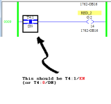
On a side note: the sequence [XIO T4:0/EN XIC T4:0/DN] (cf. rungs 0004-0008) is the same as [XIO T4:0/TT].

An even simpler system would use a single timer and use the LIM instruction to determine when lights are on; also, the green in each direction is only on when that direction's red and green are off, so you don't need a timer on the greens.
Code:
[[B]XIO T4:0/DN    [COLOR=Blue]T4:0 0.01 6000 0[/COLOR][/B]]       ### Repeating 60s timer

[[B][COLOR=Blue]LIM 5500 T4:0.ACC 5999[/COLOR][/B][COLOR=Yellow][COLOR=DarkOrange][B]  OTE YELLOW[/B][/COLOR][/COLOR][COLOR=DarkOrange][B]_1[/B][/COLOR]]  ### LIM could be [[COLOR=blue][B]GEQ T4:0.ACC 5500[/B][/COLOR]]
[[COLOR=Sienna][B][COLOR=Blue]LIM 0    T4:0.ACC 3149[/COLOR][/B][/COLOR]  [COLOR=Red]OTE RED_1[/COLOR]]

[[B][COLOR=Blue]LIM 2350 T4:0.ACC 2849[/COLOR][/B]  [COLOR=Yellow][COLOR=DarkOrange][B]OTE YELLOW[/B][/COLOR][/COLOR][COLOR=DarkOrange][B]_2[/B][/COLOR]]
[[COLOR=Sienna][B][COLOR=Blue]LIM 2850 T4:0.ACC 6000[/COLOR][/B][/COLOR]  [COLOR=Red]OTE RED_2[/COLOR]]     ### or [[COLOR=Blue][B]GEQ T4:0.ACC 2850[/B][/COLOR]]
So the reds are both on from 28.5-31.5s i.e. 3s overlap. Then the greens fill in the blanks:
Code:
[[COLOR=DarkOrange][B]XIO YELLOW_1   [/B][/COLOR][COLOR=Red][B]XIO RED_1  [COLOR=Green]OTE GREEN_1[/COLOR][/B][/COLOR]]  ### Green 1 on from 31.5-55s
[[COLOR=DarkOrange][B]XIO YELLOW_2   [/B][/COLOR][COLOR=Red][B]XIO RED_2  [COLOR=Green]OTE GREEN_2[/COLOR][/B][/COLOR]]  ### Green 2 on from 0-23.5s
Caveat: like OP's original design, this approach follows a strict 60s cycle only, and will not work if on-demand elements are incorporated e.g. crosswalk buttons, car sensors, etc.

Yeah I wont be adding any crosswalk or car sensors. This is mostly going to control some traffic lights and one railroad crossing when I can buy a house a build a flower garden to put them in. I turn the program on with a button and it runs. I do appreciate the post and see what your talking about.

The second red and green I was going to be putting in a TOF to get it to function.

I appreciate all of the help everyone is giving me totally gives me some great options to explore.
 
In the original post, there is a typo in the images of the program (this is to have no overlap between the two red lights):

xxx.png
 
Last edited:
In the original post, there is a typo in the images of the program (this is to have no overlap between the two red lights):

View attachment 59629


You are 100% correct. I found that typo right after I uploaded the images and corrected it. So its functioning. Well sort off. I have one side delayed green and the red stay on till the delay hits for the green.

Two posts back another person posted something that I'm going to try. See if that functions better. I understood what he meant by the TOF timers.

Problem I have no is when it returns from night time the other side doesn't switch to red for a moment then turn green.

So I'm gonna keep playing with it. On a side note my light towers came in which makes it a bit easier to see what this program is doing.
 
Well I will update everyone again. I'm think I'm going to give up on this delayed green thing. I can't for the life of me get the other side to stay on at all. It either kills out the red light and then turns on the green. I've tried the suggestions in here that most have posted. It would seem I can't get those to work.

So for now I'm just gonna have it once Side A turn Red Side B will turn green and once Side B turns red Side A will turn green.

I think my lack of sleep might be to blame.
 
The railroad crossing isn't done yet. I don't even have a crossing signal to make this work yet. I will eventually get that working. For right now I'm working on the traffic signal part. That is for cars that is.

Eventually when I do the program for the train crossing when I push a button it will latch, turn on the crossing signal lights, gate will lower after about 5 seconds of the lights coming on. After about 3-5 minutes the gate will come up and shut off the lights on the train crossing signal and return the traffic lights back to regular operation. I would like to even do a preemption cycle as well but I feel that is going way further then what I know on PLCs.

Someday I plan on getting another micrologix controller and building a model train setup and using it to control crossings, traffic lights, and lighting for the model.

Right now just working on the setup for my future backyard project.


I documented my progress on my website here. You may find some useful information when you start planning to do the layout.


https://www.nepaview.com/model-train-plc-project.html
 

Similar Topics

hello everyone i was thinking about starting on a new project on my RSLogix 500, i was going to be doing a traffic project! however, i am a little...
Replies
3
Views
1,805
I am trying to simplify my program to not use the GEQ and LES functions. Can I substitute timers for this?
Replies
8
Views
5,093
I have a network with 4 PLCs PLC1 is controllogix and PLCs 2-4 are compactlogix and they all need to communicate. The current way I have this...
Replies
8
Views
265
So to start off: I have no experience with PLC's, but I'm good at figuring stuff out, but I need some help to know if my PLC is just dead in the...
Replies
2
Views
118
Back
Top Bottom