cannot get 1771 NOC/A to accept I/O edits

sparkytex

Lifetime Supporting Member
Join Date
Jun 2013
Location
Port Hardy B.C.
Posts
354
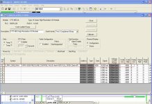
I'm trying to do some scaling for my PID output that I had just programmed and am having issues getting the analog output card (1771-NOC/A) to accept edits. The scaling was set for 4000 (4mA out) and 20000 (20mA out) for raw data. Since the PLC-5 PID instruction will only send out 4095 for its max output this will only give it our valve 4 mA at a command of 100% from wonderware. I attached a screen shot of what I'm talking about as well as the program itself.

as you can see in the screen shot I've changed the scaling from 4000-20000 to 0-4095 and with a 100% signal from wonderware I'm getting 4095 to the output and 20mA is said to be written out to the valve. I'm only getting 4mA out of the card which means its still stuck with its old scaling. I also changed the scaling back to 4000-20000 and send 4/12/16/20 mA's out and I could read every value correctly. But as soon as I go to 0-4095 I can only put out a max of 4mA and when the signal from wonderware is at 0% I get 0mA out of the card.

I pressed enable edits and accepted the edits I made and downloaded them to the processor but still no change. Can some one please shed some light on what I'm obviously doing wrong.

thanks.
D-PIC-3030.jpg
 

Attachments

  • DIGPLC21.zip
    287.1 KB · Views: 8
I pressed enable edits and accepted the edits I made and downloaded them to the processor but still no change.

but ...

did you then INITIATE/TRIGGER the Block Transfer Write instruction to "send" the new scaling information over to the module? ...

post the correct program and we'll try to take a look – but I'll bet (pocket change only) that you didn't execute the all-important Block Transfer Write instruction AFTER you made the desired scaling changes ...

basic idea:

the module's configuration data is "stored" in the PLC processor – but that data must then be "sent" over to the analog module before the configuration (or REconfiguration) of the module takes place ... a Block Transfer Write instruction is the "mailman" that delivers the configuraton data FROM the PLC processor TO the analog module ...
 
Last edited:
but ...

did you then INITIATE/TRIGGER the Block Transfer Write instruction to "send" the new scaling information over to the module? ...

post the correct program and we'll try to take a look – but I'll bet (pocket change only) that you didn't execute the all-important Block Transfer Write instruction AFTER you made the desired scaling changes ...

basic idea:

the module's configuration data is "stored" in the PLC processor – but that data must then be "sent" over to the analog module before the configuration (or REconfiguration) of the module takes place ... a Block Transfer Write instruction is the "mailman" that delivers the configuraton data FROM the PLC processor TO the analog module ...

Ok I attached the correct program this time, my apologies I've be quite flustered as were starting back up from a scheduled maintenance shutdown and a lot is happening.

Ron how do I "initiate/trigger the block transfer write instructions to send the new scaling info to the module"?
 
Programming looks good, can you take a snap shot of the program when you are writing to the output word N119:2?

You can make the rung go true by using a manually controlled bit and toggling it on momentary. Branch around the existing instructions.
 
Last edited:
Programming looks good, can you take a snap shot of the program when you are writing to the output word N119:2?

You can make the rung go true by using a manually controlled bit and toggling it on momentary. Branch around the existing instructions.

do you want a snap shot of the I/O config when I am manually writing to N119:2 or do you want a copy of the program while I'm writing to N119:2?
 
Copy of the program, it will show the I/O configuration also.

Have you actually measured the 4 to 20ma output with a meter?
 
Copy of the program, it will show the I/O configuration also.

Have you actually measured the 4 to 20ma output with a meter?

Yes I had an instrument mechanic verify it with a meter. at 4095 raw data and "20mA"'s it was only putting out just over 4 mA's from the card. As soon as I changed the scaling back to 4000 min to 20000 max and accepts edits I could write 4/12/20 mA's no problem. For some reason it just wont accept the new edits and just remains with the old 4000 min raw to 20000 max raw.

I attached a copy of the program with the output scaled from 0-4095 with a forced written value of 4095 in N119:2. As you can see the card "says" it putting out 20 mA's when we verified with a meter it is not.
 
That still doesn't tell us that the actual configuration has been written to the card, as Ron pointed out. Have you tried to manually make the run with the "BTW" for that card go true?

A work around if you cannot get the card to accept the new configuration is to rescale the PID's output to 4000 To 20000

N119:2=(PID Output*3.907)+4000
 
Last edited:
yes I'm still having issues with this card, i'll try manually making the rung with the BTW go true, as well as keeping in mind about having to scale the PID's output. Also is there any jumpers associated with this card that need to be configured before installation? I'm currently looking for the manual for the 1771 NOC/A card.
 
Have you tried putting a value in the clamp high spot? It may or may not help, I'm not familiar with that particular card, it might be worth trying.
 

Similar Topics

Hello everyone, I am currently working on a project that uses a Rockwell L33ER controller and the FTV Studio V13 as Supervisory computer...
Replies
0
Views
128
Hello Friends I have a backup that I am trying t open in mi PC (RSLogix 17.01) and I get this message. I have read many posts and done many...
Replies
1
Views
168
Hi, Im trying to open an old old Siemens WinCC project. It doesnt have to run i just want to look at the project in WinCC explorer. Its...
Replies
2
Views
667
Hello. I cannot change the SendClock settings for a PROFINET IO device. I need to slow down the CODESYS PROFINET IO controller. What am I doing...
Replies
0
Views
199
Hi, I received the following project from a customer on a QuickPanel Proface 6" that I need to swap to a Siemens Panel. However, I cannot seem to...
Replies
3
Views
338
Back
Top Bottom