Alternating Pumps

dronai

Member
Join Date
Aug 2011
Location
Calif.
Posts
145
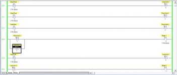
I've programmed this AB Micro Logix 1000 to mimic an alternating pump sewer lift control electronic board.

This does everything I want including latched floats until the tank is drained to the stop float.

There is a lead float which I want to alternate. There is a lag float, which controls both pumps, in case the lead pump fails. I will add an alarm and siren for high level.

I'm stuck on making an alternating circuit controlled from one input. I looked at the examples posted here, and tried to use them including the counter, and one other, but no success. I need it to latch so the pump doesn't cycle.
 
Last edited:
It sounds like the LogixPro Dual Compressor solution would work for you. I will find a picture of that solution and post it when I find it.

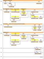
EDIT: Here is the picture. The B3:0/1 bit is the alternator. Use your lead float switch where the I:1/2 Pressure Switch is now. Use your lag float switch where the I:1/3 Pressure switch is now. Rung 002 is the alternator, but note that you must have the "C1 HAS RUN" latch on the first pump to run, and the Unlatch bit on the second pump to run.

The T4:2 timer and the subroutines should not be needed for your application.

Dual Compressor Exercise 4.jpg
 
Last edited:
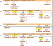
If you want the pumps to go on when the float contacts close (opposite of the dual compressor pressure switches), then change the logic as shown in the attached picture. This version seems to work on the LogixPro simulator software.

Alternating Pump Sewer Lift Control- Dronai.jpg
 
Last edited:
Thanks, going to load that and give it a look. Way more complicated than I imagined ! The lag float trigger should make both pumps go until the stop float unlatches both pumps.
 
Last edited:
The lag float trigger should make both pumps go until the stop float unlatches both pumps.
Yes, that last version (after I added the Stop Float and seal-in contacts for each pump) works just like that. My Rung 003 comment should now be changed to read "When Lag Float goes ON, both pumps will run until the Stop Float goes ON."

Complicated? It only required 3 rungs (doing without the optional System Run bit). You could use latching bits for the two Pump Outputs (requiring then 2 latching and 2 unlatching rungs for the Pumps), and split the logic into about 6 or 8 simpler rungs, but would that really be any less complicated?

If you examine each Pump Output rung, they really consist of the old common standard Stop-Start motor starter logic, with the series Stop bits on the left side, the parallel Start bits in the center, and the Motor Run bit on the right side. Then you add the alternator inhibit bit to the Start logic and the "motor has run" bit in parallel with the motor output bit. That's it.
 
Last edited:
Working ! Sorry pilot error, I had one of the contacts N/O by mistake.

Thanks for your help. This puzzle has had me going for awhile.
 
Last edited:
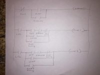
This is how I do my pump alternating. I don't have my work laptop at home so I apologize for the rudimentary drawing. This also works with hard wired relays too without any special relays.

image.jpg
 
Nice one Scameron81 ! Your from Electricians talk yes ?

I'll wire that one with icecube relays for fun

What does your abbreviations stand for ?
 
Last edited:
What does your abbreviations stand for ?
I think I can answer that because they are fairly common when working with level switches.

LSL = Level Switch Low
LSH = Level Switch High
LSHH = Level Switch High-High (level is too high, near overflowing)

Notice that there is no "Stop" level switch as in your scenario. The LSL does the stop function in Scameron's drawing, because as the pump lowers the level, LSL is ON at high level, but goes back off at low level. That is efficient if your level swtiches are designed to work that way.
 
Last edited:
I think I can answer that because they are fairly common when working with level switches.

LSL = Level Switch Low
LSH = Level Switch High
LSHH = Level Switch High-High (level is too high, near overflowing)

Notice that there is no "Stop" level switch as in your scenario. The LSL does the stop function in Scameron's drawing, because as the pump lowers the level, LSL is ON at high level, but goes back off at low level. That is efficient if your level swtiches are designed to work that way.


When I was bench testing my electronic pump controls, I noticed when I took the jumper (simulating closed float) I had on the lead and lag floats terminals off, the pumps would continue to run until the stop was triggered. Indicating a latch. I think this is smart to prevent cycling in a water tank with motion.

I work with these every few months. I noticed the newer models have a 4 float system with the high level for alarm and siren, But an older 3 float system, had the alarm/siren gong on with the lag float trigger. I think this is better, letting you know that either a float is not closing on the lead, or a pump has failed, and there is no back up.
 
One thing I noticed about Scameron's circuit is that if Pump 1 is running, and the LSHH switch goes on, starting both pumps, then the next time, Pump 1 always runs again, even when it is time for Pump 2 to start. In other words, the alternator is looking at Pump 2, not strictly at the level switches to determine whose time is next. This is not a big problem, because during normal cycles the pumps will alternate, but it is a quirk to be aware of.
 
Last edited:
With relay logic, scameron's drawing would take 9 NO contacts, and 3 NC contacts to make. 2 test switches
 
One thing I noticed about Scameron's circuit is that if Pump 1 is running, and the LSHH switch goes on, starting both pumps, then the next time, Pump 1 always runs again, even when it is time for Pump 2 to start. In other words, the alternator is looking at Pump 2, not strictly at the level switches to determine whose time is next. This is not a big problem, because during normal cycles the pumps will alternate, but it is a quirk to be aware of.

That's true it does have that quirk. Also if one of the pumps is not in auto, then the other pump will never start until you get to the high high level. We usually bypass the alternate with a "other pump not in auto contact from the control switch"

Dronai: Yes hardwired it is a ton of contacts and wires. We have about twenty pump stations hardwired like this, but they last forever and never fail. The ones with the electronic alternating relays bomb out all the time on us. Anything new is done with PLC's now using a level transmitter.
 
Last edited:

Similar Topics

I have 2 pumps not alternating at a lift station. When im at the panel and use the test switches to initiate the pumps,it alternates in the PLC...
Replies
22
Views
5,837
Hello I have been thinking in some way to operate 3 pumps in the same way (I have schneider modicon m340 PLC): -the pumps feed a tank. - As...
Replies
3
Views
1,880
I need to create a system of 2 alternating pumps in ladder logic. I am using RSLogix 5000 2 pumps controlled in 3 modes (OFF, Manual and Auto)...
Replies
46
Views
26,874
Hello all. I have been trying to build a program to alternate three vacuum pumps that will have a lead and two backups. Back ups will come in at...
Replies
5
Views
3,017
Today I was making an online edit to a 5/40 Series E Rev K.2 with about 14% free memory. I was removing one branch in a large rung. Accept...
Replies
4
Views
3,168
Back
Top Bottom