OT: Variable disp. hyd. pump symbol

strantor

Member
Join Date
Sep 2010
Location
katy tx
Posts
401
I'm looking for the basic schematic symbol for a pressure compensated variable displacement hydraulic pump (swashplate type radial piston pump) that has external hydraulic pressure setpoint (adjustable relief valve).

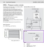
Here is the ground-level diagram provided by the manufacturer of the pump:

attachment.php


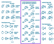
but that's too detailed for an overall system drawing. I'm using MS. Visio to do the hydraulic schematic, and it gives me these choices for variable displacement pumps:

attachment.php


I can edit these symbols to get what I want, but I really don't know what to edit. My first thought was to edit the "manual override" symbol and replace that "block" thingy with a pilot line to a pressure relief valve, but I don't know if that would be correct.

Any insight from those around here knowledgeable in hydraulics?

Thanks,
Strantor.
pressure pump.jpg pressure pump2.png
 
Look again at the manufacturer's drawing.

For a simplified symbol use only the circle with a triangle showing the discharge port, suction port, and the crossing arrow at an angle. Don't include the compensator piston or spring at the ends of the arrow. There is no need to show the motor shaft unless you also show the motor, and no need to show case drain unless the case drain has flow instrumentation.

That said, I prefer to show the full pump controls on a hydraulic diagram as it provides useful information about the compensator controls to the hydraulic technician.
 
Last edited:
Look again at the manufacturer's drawing.

For a simplified symbol use only the circle with a triangle showing the discharge port, suction port, and the crossing arrow at an angle. Don't include the compensator piston or spring at the ends of the arrow. There is no need to show the motor shaft unless you also show the motor, and no need to show case drain unless the case drain has flow instrumentation.

That said, I prefer to show the full pump controls on a hydraulic diagram as it provides useful information about the compensator controls to the hydraulic technician.

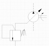
Well I wanted to show the remote pressure adjustment on the diagram since it is an adjustment which is included in the start-up procedure. This diagram will be attached to the startup procedure, and critical adjustments like this pressure setpoint will be highlighted.

The nitty-gritty drawing like what is shown in the manufacturer's manual above, - the kind that the hydraulic technician would use - will be separate drawing.
 
This is what I was talking about in the first post.
Would this make sense to you if you saw it? Or is it total nonsense?


attachment.php


pressure pump3.jpg
 

Similar Topics

I'm upgrading an existing machine with a Honeywell HC900 controller, and I'm trying to do some data processing in the controller. I have variables...
Replies
0
Views
56
dear all.. i am designing the Sea Water Intake pump which the 4 pumps will be operated parallel, and 1 pump will be as stand by pump The pump data...
Replies
3
Views
157
I have a old lathe with a 120 VCA 9.5 AMP motor. Has white, black and red wires. I need to find a way to connect it to a variable speed controler...
Replies
0
Views
96
I am trying to display a variable within a cicode function onto a graphics page. This function queries a SQL database. I can get the value onto a...
Replies
3
Views
288
Hi all. I'm running a VBA code on my FTView which is actually working, but everytime I open the display that calls the VBA code, it throws the...
Replies
28
Views
1,806
Back
Top Bottom