PLC panelview Block transfers

Alper

Member
Join Date
Dec 2014
Location
The North
Posts
14
Hi guy.
well im having a hard time figuring out how to make a numeric entry in an already made PV program but i've never worked with scanners and RIOs so hopefully you'll give a hand with this
i want to modify the LAD 18-TC11 of the program to modify the number of cycles by means of a numeric entry in the panelview
 
You didn't start out with an easy application !

The PanelView 600 application is small, but the SLC-500 application looks like it handles quite a lot on the RIO network using that 1747-SN scanner module in Slot 19.

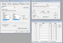
The PanelBuilder32 communication configuration screen tells us that the PV600 is configured to be Rack 2, Groups 4,5,6,7 on the RIO network.

It also tells us that the SLC is using Block Transfers to exchange data with the PanelView, and that the Block Transfers use SLC-500 data files N111:31 to Read 2 words of data from the PanelView to the SLC and data file N111:1 to Write 14 words of data to the PanelView.

Those N111:1 and N111:31 addresses entered into that window are purely for descriptive purposes in the PanelView. The PanelView just knows its getting a Block Transfer of a certain Read and a certain Write length, but it lets you use those addresses in the Tag Database to remind yourself where they're going to appear in the SLC-500 data table.

I'm going to attach an illustrative screenshot of the PanelBuilder32 comms configuration to this post, then move on to the RSLogix 500 program.

PV600_RIO1.jpg
 
I'm going to try to narrowly focus on the objects and addresses that are used by the operator to enter data into the PanelView so that it appears in the SLC-500.

There's not much data being exchanged in that direction. There's the discrete data that makes up the Input and Output data tables associated with Rack 2, Groups 4,5,6,7, and there's that one small Block Transfer Read that takes just two 16-bit words of data from the PanelView into the SLC-500.

Most of that data is already used in the PanelView application, as seen by reading the Tag Database.

station_11_auto_cycle I:19.21/0
station_11_blower I:19.21/1
station_11_water_pump I:19.21/2
station_11_manual_cycle I:19.21/3
station_12_auto_cycle I:19.23/0
station_12_blower I:19.23/1
station_12_water_pump I:19.23/2
station_12_manual_cycle I:19.23/3
Station 11 Motor Mode N111:31
Station 12 Motor Mode N111:32


Notably, only two of the four available Input data words are used.

For a 1747-SN located in Slot 19, the discrete I/O data is addressed with 8 words per "Rack". Rack 00 is words 0-7, Rack 01 is words 8-15, and Rack 02 is words 16-23.

So there are two 16-bit words that are available in your PanelView application, I:19.20 and I:19.22.

You could just create a new Tag named "Cycle_Qty" in the PanelBuilder application and address it as I:19.20, and just use that address in your SLC-500 program.

Or, you could increase the amount of data being exchanged by that Block Transfer Read. More on that... when our program returns.
 
If it were my system, I would increase the size of the block transfer so I had more data to work with.

There are five basic things you need to modify to do this:

1. In PanelBuilder32, change the size of the Block Transfer that the PV600 expects.
In the project tree, select Communications Setup -> Comms Setup button -> Block Transfers button. Change the first Block Transfer (the Read) from 2 words to 10 words.

2. In PanelBuilder32, create a Tag with the data you want to use. In the project tree, select Tag Editor, then hit Insert.
Give it a name like "Cycle_Qty", select Unsigned Integer as the datatype, and address it to N111:30.

3. In PanelBuilder32, create the Numeric Entry object for your "Number of Cycles" entry. I would use a Numeric Entry Keypad Enable object, and address the Write tag to N111:30.

4. In RSLogix 500, change the configuration for the Block Transfer Read.
In Ladder File TC11_BT, the first rung configures the Block Transfer for this PanelView terminal using the data stored in N111:50, 51, 52.
The value in N111:51 is the Length of the block transfer. Change this from 2 to 10.

5. In RSLogix 500, change the amount of data copied out of the BTR result buffer.
In Ladder File TC11_BT, Rung 5 grabs the data from the BTR result buffer and puts it into N111:31-32. Edit that rung so that the Destination address is N111:30 and the Length is 10 instead of 2.


Download those changes, of course, to the PanelView and the SLC-500. You can do those SLC-500 edits online if you wish.

BT_Config_Size.jpg
 
A screenshot of the changes necessary to Rung 5. Only N111:31 and 32 are used right now, so I recommend taking up a nice healthy ten-word block of that data table for your block transfer needs.

Remember to change the destination address (N111:30, not :31) and the Length (10, not 2) as well as the size in the BTR configuration block (N111:51 = 10, not =2).

BT_Config_BufferCopy.jpg
 
A screenshot of the changes necessary to Rung 5. Only N111:31 and 32 are used right now, so I recommend taking up a nice healthy ten-word block of that data table for your block transfer needs.

Remember to change the destination address (N111:30, not :31) and the Length (10, not 2) as well as the size in the BTR configuration block (N111:51 = 10, not =2).
Tried change the program but it didnt worked. even worst
now i have an issue with other PV that now is not working.
somehow other panelview is showing the error 208 unable to write to remote device.
 
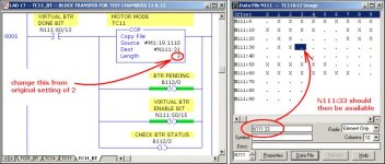
I suggest that you go back to the ORIGINAL program files that you posted above ...

then try this at the SLC end ...

.

SLC_End.jpg
 
Last edited:
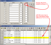
and try this at the PanelView end ...

note that I agree with Ken - personally I'd set up some "extra" locations ...

but ...

for right now, let's just get it going with minimal intervention ... the method that I've shown here should leave the original connections working - and only add one more location to your Block Transfer Read operation ...

add whatever type of data entry that you desire so that the operator can change the new tag "number_of_cycles" and see if the value entered pops up at location N111:33 ... once that happens, then you should be able to use that value in your SLC program ... let us know if you need help with that piece of the puzzle ...

.

Block_Transfer.PNG
 
Last edited:
Great i worked guys.
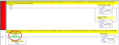
first i was trying to fix the problem with other station that stopped working and i didnt even touched it. turned out that either the changed station and the faulty station had to be started manually from the BTR pending bit.
Thank you all.

Untitled.jpg
 

Similar Topics

Hello, I have a machine with a 1756-L72 Controllogix PLC and 1756-EN2T network card, and PanelView Plus 7 HMI. I am using RSLogix V20.05.00...
Replies
12
Views
768
merry christmas and happy new year i have a click c0-00dr-d and allen bradley 2711c-t3m. can the panelview talk to the click plc via modbus...
Replies
1
Views
179
Hello all! Can someone shed some light on this? I am trying to connect a PVP 6 to a PLC-5/30 through the serial ports because the old touch...
Replies
2
Views
477
Hello, We have an older machine that has a standard PanelView (2711-T10C3) connected over DH485 to a SLC 5/04 PLC via a 1761-NET-AIC module in...
Replies
1
Views
648
Last night electricians replaced the panelview and now there is no comms between the panelview and the PLC. The processor is a 1747-L541 SLC 5/04...
Replies
4
Views
880
Back
Top Bottom