Help with Analog BTR MSG instruction

electric101

Member
Join Date
Sep 2015
Location
Alabama
Posts
27
The good news is I became a dad today, i'm posting from the hospital at this moment.
the bad news is i've still not figured out reading my analog data on this devicenet FLEX IO system.... all my other posts go unanswered, but i think that might be because of the complexity of which i composed the question.
i've made some progress so maybe its simplified now
I just need to know that what i've got going here is in the right direction.
and if that answer is yes i need to know how to determine the data that goes in the communication tab basically to path out the read to the module. Channel? , rack?, group?, slot?

here is my .dnt file and my .vcd file which should tell you all the actual hardware being used.

thanks guys.
 
First
Congratulations on the newborn hope both are doing well
But why are you at the hospital doing work when you should devote all you time to your family at a time like that, work can wait if your boss doesn't understand that then get a new boss because that job is going no ware.

Now for your PLC problem
The first thing I see is that you are using FlexI/O on Device Net but you are trying to use messaging on Remote I/O they are 2 entirely different networks. In device Net you read the data in the scanner module the scanner module takes care of the communication with all the I/O
You need to look up the scanner configuration and select the data you want.
 
GaryS,
First thanks for just replying! I work with alot of excellent automation programmers, but we use hardware and applications that dont remotely resemble ladder logic. so, I know alot and am surrounded by a lot of smart people but i have no one to ask about allen bradley PLC's.
second,
I'm leaving my current job to take over support at a medium size plant that uses all controllogix with flex IO and lots of robotics. I'm trying to get and be as prepaired as i can be when i walk in the door. I've been working on my test bench setup at home just to learn everything better and i'm hung up on this analog input/output... and when i hit something i cant figure out... i just cant get it out of my head.
I've asked for an example in posts but never got a real reply. I've read the doc on the modules but the only msg example it gives is in PLC5 and i'm using RSlogix5000.
So, should i not be using a msg instruction at all? because i noticed on the communications tab there was no devicenet option... just RIO and controlnet.

The baby and family are doing great... i'm just taking a sec to check the msgs :)
Thanks again for taking the time to have a look and help me out.
 
Your Welcome
the PLC5 used block transfer to read and write to the smart modules. When the 5000 system came out the have a different communication but can use the old hardware but in place of the block transfer you now have to use a messaging command. you can cross over the networks but it is tricky the network you show is Devicenet the scanner module takes care of the communication to each device and places the data in the scanner tag you ladder program reads / writes to the scanner tag
 
congratulations on the fatherhood ...

probably the main reason that you're not getting many replies is that you're using a SOFTLogix system - not real-world hardware ... most folks here don't use - or have any experience with the "soft" stuff ... plus the 1784-PCIDS card that you're using for an interface is not all that common (frankly I had to look it up to find out what it is) ...

I happen to have some DeviceNet gear in my home lab equipment right now - so maybe I can work up SOMETHING that MIGHT be helpful to you ...

the more you tell us about what you're trying to do - and WHY - then the more detailed we can make our answers ...
 
I went back and took a closer look at your network
The flex I/O is mapped to the controller tags as shown below
No messaging required
You just read and write to the controller tags
Input
Flex_combo_input_data[0] 1794 AND Status Bits
Flex_combo_input_data[1] 1794 IB16 /A Bits
Flex_combo_input_data[2] 1794 –IF2XOF2I/OA Channel 0 Input Data
Flex_combo_input_data[3] 1794 –IF2XOF2I/OA Channel 1 Input Data
Flex_combo_input_data[4] 1794 –IF2XOF2I/OA Channel 0 Output Read Back
Flex_combo_input_data[5] 1794 –IF2XOF2I/OA Channel 1 Output Read back
Flex_combo_input_data[6] Not Used
Flex_combo_input_data[7] Not Used

Output
Flex_combo_output_data[0] 1794 OB15/A Output Bits
Flex_combo_output_data[1] 1794- IF2XOF2I/OA Channel 0 Output Data
Flex_combo_output_data[2] 1794- IF2XOF2I/0A Channel 1 Output Data
Flex_combo_output_data[3] Not Used
Flex_combo_output_data[4] Not Used
Flex_combo_output_data[5] Not Used
Flex_combo_output_data[6] Not Used
Flex_combo_output_data[7] Not Used

I hope this clears things up
 
Yeah, i thought the fact that i was using the soft logix would throw people off... but the company i work for bought a company that used that in their batching systems and we have replaced them with our hardware so i was able to get the stuff for free.
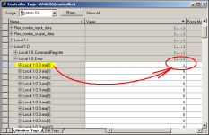
one key piece of info i'll attach.

and theres this that i know for sure:
the output bits are as you have listed for the OB16/A outputs but:
Local:1:I.Data[0].0 - Local:1:I.Data[0].15 (controler input data)
Local:1:I.Data[0]16 - Local:1:I.Data[0].32 (IB16 16 input bits)
I have turned on the system and watched the bits from Local:1:I.Data[1].0-32 and never saw any of those bits change from 0 while varying the voltage on the input channel from 4-5vdc... thats when i began searching for alternate ways... just because i thought i must not be doing something right. maybe i need to look at Local:1:I.Data[2].0 - Local:1:I.Data[2].32

thanks again guys!!!

capture2.JPG
 
Last edited:
But your I/O is connected to a IF2XOF2I/0A on the Deicenet not the local rack
the tag "Local" refers to the Local Rack only the FlexI/O is on the Devicenet network they will be different tags.
look at the data in Controller Tags Flex_combo_input[2]
as shown on my previous post.
 
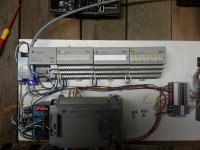
oh and Ron, i'm setting this all up in my home test lab also and just to learn rslogix5000 better. i'm ok with rslogix500 using micrologix 1500 but not yet had any experience using analog with that either. 3 months ago i knew nothing about PLC coding. I'm great with relay logic, anything IT related, and programing our batching system... i can making anything happen with our custom equations software but i'm just getting started with this... but its imperative that i do....and quickly. so in short just want to see my analog signal in the logic... maybe use it with a compare or greater than statement to build a temperature control system for my farms water tanks. this is what i have.

IMG_20150930_195121.jpg IMG_20151006_203341.jpg
 
Last edited:
i think because of this 1784 scanner card it sees it all local... because my 1794-OB16 and my 1794-IB16 are also connected to the devicenet as well as the IF2XOF2I and the ob16 and ib16 are working on the local tags. i created the flex_combo_input myself just trying an idea... i'm going to get rid of it so as not to cause confusion.
 
That would make sense the I/O could be all shown as local but the data layout would be as I show in the previous post just switch the Flex Combo with Local I would expect it to work OK
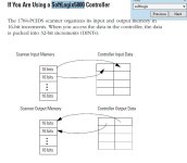
you may want to note that all Devicenet modules communicate with 8 bit words only usually analog data is received by the scanner module as 2 word and assembled into 1 16 bit word for the processor.
if you look at the configuration od the PCIDS module it show the I/O as local I don't know what would happen if you had more than 1 PCIDS module you would need on if you have more than 32 devices in the network (Devicenet addressing limit )
Good luck
 
I just did a test and added a 2nd PCIDS module and it assigns that on to Local:3 the original is assigned as Local:1:I and Local:1:O
Slot number are part of the tag addressing
 
if all else fails, try turning on the bit shown below ... notice that this is in an OUTPUT location for your Channel 0 INPUT ...

I've been experimenting with a 1794-IE8/B (different from your module) on DeviceNet – but nothing good happened until I flipped that "configuration bit" on ... then suddenly I started getting input signals ...

page 92 in the following manual might be helpful ...

http://literature.rockwellautomation.com/idc/groups/literature/documents/um/1794-um008_-en-p.pdf

note that I'm basing my GUESS on the information you posted earlier ... if you've rearranged the "mapping" then the bit location might have changed ...

good luck with your project ...

.

configure_ch_0.PNG
 
still havent gotten it working but i think i'm going to try to remove all other modules and just concentrate on getting the analog working by its self... at least that will remove some of the mapping options.
 
when the baby is about six weeks and it learns to look you in the eye and smiles cause it knows who you are, work gets to be a second thought.

when the baby gets about seven months and learns to walk by your tutelage, then smiles and rejoices at you, work gets to be a second thought

when the baby gets to be about fifteen months old and the utterable whispers of "da'da" start coming out, work gets to be a second thought.

when you come home at the end of the day and they run into your arms, work gets to be a second thought

Do yourself a favor, when you at home, be at home.

Just so it fits into the thread....................your holding the ultimate I/O package there

Congrats on daddyhood
 

Similar Topics

Hi, I have a bit of PLC experience in Siemens and have unfortunately been blessed with working on Automation Studio and B&R which has been a big...
Replies
5
Views
1,364
We have an omron CJ2M-CPU12 PLC that we are having issues with an AD04U analog card. it is connected to a K type thermocouple sensor. The card is...
Replies
4
Views
600
Hi all, While i am not new to omron, i'm totally new to the analog part and lost. i have a CJ2M cpu 33. then there are 4 i/o cards card 5 is a...
Replies
26
Views
2,583
Hi I have a modicon 984 with proworx 32 that is scaling an analog input, and I need to adjust the scaling. I have new analog input values and %...
Replies
3
Views
1,727
I have a Mitsubishi FX2N-64MR-UA1 processor. The 1st analog output card is an FX2N-4DA. It requires 24VDC power. That card is obsolete. The card...
Replies
1
Views
1,576
Back
Top Bottom