Omron CJ2M and MAD42 analog card help

drbitboy,
it's a windows 10 pro laptop set up by IT department.

so far i understand the following.
Unit # and voltage / current dip switches.
DM addresses - this sets up how the module is used.
CIO addresses is where the data in the analog is located.
i do not understand how to configure the conversion data holding addresses
for example C2015 to C2018 is stored in D00100 to D00103 (from the manual).
How do you get the D numbers?
the CIO numbers range from 2000 + (n*10) to 2000+(n*10)+9
where n is the unit number.
HOW do you compute the corresponding D numbers??
If someone would explain that and post examples with comments it would be much appreciated. the omron manual jumps around and does not detail events in order.
i thought the munitions plant where i worked was strict about things, this plant is worse, but at least the IT department does not control my programming laptop!
There is no sort of order as to how programs are stored or named. everyone had their own method. now it's just me doing everything and learning omron, siemens, fanuc, sew, and a few other things at one time.
does anyone know of good omron plc tutorials?
thank you all,
james
 
drbitboy,
so far i understand the following.
Unit # and voltage / current dip switches.
DM addresses - this sets up how the module is used.
CIO addresses is where the data in the analog is located.
Yep, corrrect so far.

i do not understand how to configure the conversion data holding addresses
for example C2015 to C2018 is stored in D00100 to D00103 (from the manual).
No.
CIO2015-2018 is where the raw data for channel 1-4 is located. 2011-2012 is where the raw data for the output channels 1-2 should be written

How do you get the D numbers?
the CIO numbers range from 2000 + (n*10) to 2000+(n*10)+9
where n is the unit number.
HOW do you compute the corresponding D numbers??
There is a similar formula, but they are also shown in the module setup under the IOTable.
This is probably easier rather than the coding examples to get the understanding at least.
As an FYI, you can also move the HEX equivalent #FF instead of &256 etc.. this makes it easier to read for this IMHO


You have made some good progress.
Can you update us as to where you are up to.? What is working, what is not etc?
 
As with the CIO area, the DM area is 20000 + (n x 100) for special I/O units. But as LC says, much easier to find via module setup.
 
where i am having trouble is how you determine the storage numbers for C2010 to C2019.

for example C2015 to C2018 is stored in D00100 to D00103 (from the manual).
this is unit 1.

what if this was unit 3? the CIO numbers would be C2030 to C2039.
where would you move these data registers in order to use them ?
how do you determine the register numbers?

in my program i have the following
Power_ON mov &243 D20100 ( enable the i/o card)
Mov &42505 D20101 (tell the card how it will be used)
Mov &194 D20135 (can't remember)

Do i need these statements in the program since i used the software to tell the card how it is used? i do not see this in the card (or at least in the part of the program i looked at) where the analog routine was.

the next thing is for me to determine what the attached picture represents. AB is not new to me, but this is harder than it looks.

i really appreciate everyone's help!!
thank you so much,
james

MAD42.jpg
 
Last edited:
where i am having trouble is how you determine the storage numbers for C2010 to C2019.
This is based on 2000 + (n x 10).


for example C2015 to C2018 is stored in D00100 to D00103 (from the manual).
this is unit 1.
The manual shows an example of copying the CIO area to DM area for program use. You do not have to do this.


what if this was unit 3? the CIO numbers would be C2030 to C2039.
Correct.

where would you move these data registers in order to use them ?
You do not need to.

how do you determine the register numbers?
For D100-103 etc as per the manual, these are whatever you select (that are not already used or pre-allocated

in my program i have the following
Power_ON mov &243 D20100 ( enable the i/o card)
Mov &42505 D20101 (tell the card how it will be used)
Mov &194 D20135 (can't remember)

Do i need these statements in the program since i used the software to tell the card how it is used? i do not see this in the card
Not really, it is just a legacy practice to set the card up as opposed to using the IO Table. It is like a brute force method so will always return to that when PLC starts..


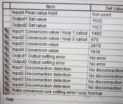
The picture shows the current values in CIO2011-2018. To me, it looks like you are reading values on all inputs, so that is a good thing.
You are also writing to CIO2011/2012 as well OR have set the values manually. Either way, you should also have a value on those output terminals.
 
[need these statements in the program since i used the software to tell the card how it is used? i do not see this in the card (or at least in the part of the program i looked at) where the analog routine was.
[/QUOTE]

Hard coding the configuration is fine if it's not going to change. However after months/years of not touching then wanting to change/add an input/output you'll need to dig up the manuals again. Also configuration changes only take affect after a power cycle or unit restart. Unless you code it in from the start try to remember A502.00-15 is the unit restart bits for special I/O units. On the other hand in the I/O table setup there is nice restart button.
 
lostcontrol,

i forgot to mention that the picture was from the existing program that was offline. i do apologize for not stating that earlier.
thanks for letting me know about the cio to data register storage.
i thought you had to move c2015 to d100 in order to use the data. is that correct?
my next issue will be how to scale the data and offset values.
i will post my progress later today.
thanks for your help and to everyone else!
james
 
Last edited:
this is what i have so far this morning.
on my test bench i have a pot going into input 1 of my mad24 card.
the input is enabled, set to 1-5 volts
i am watching the data change in the data monitor word D100, the word is set to signed decimal channel.
here is my issue, from 0 to 1 volts, the reading is negative.
from 1.01 to t volts, i get a positive number.
how do i get my plc to read 0 to 5 volts on the input? i am guessing you don't since the setting is 1 to 5 volts. Am i correct?
how would i get a data register to read 0 to 5 volts which represents 0" to 5" of distance?
thanks in advance,
james
 
why 1-5?
if you want 0-5, why not change the input to be 0-10?

the word is set to signed decimal channel.
On this, CX-P allows for you to view in Hex, signed & un-signed.
You value will be counts in the range 0-4000.

my next issue will be how to scale the data and offset values.
This is very easy. Do you want real world units?
 
to be honest with you, I should have. I am hung up on getting the 1-5 volt signal working.
This is what I have working.
Input 2 is enabled and set to 0-10 volts. This is unit 1 and the dm address is D20100 on. The CIO address is 2015 to 2019 and the conversion registers are D100 to D104.
we had a sensor go bad on a line and since i am new to the omron analog scheme, i am working with the unit in my office as a trainer.
There is a pot (this is all I have in the office) connected to input 2 that will supply 0 to 3.73 volts and I can see that number in D101 (373). This input is for a slurry tank that has min and max limits.
What I am trying to do is when the voltage is 0, we read 0 cm and when the input is 3.73 we need to read 30cm on an hmi display. We turn on a valve when the level is at 5 cm and off when the level is at 23 cm.
I want to multiply the input reading by 8.042895 and place it into a register to read the value of cm.
(10/373) x 3 = 0.026809
I’m having trouble with the multiply statement *F.
Multiply D101 x 0.026809 and place it into a register.
Also, is there a conversion (function block) . if so, please post both
regards,
james
 
Do use floating point, you need to convert it first
FLT D101 Dxxxx
*F Dxxxx +0.02688 Dxxxx1

Note:
Dxxx & Dxxx1 are 2x consecutive words so you need to allow for this (this is PLC fundamental outside of rockerweller..)

Does your HMI use floats? If not, you will have to convert back but probably best to multiply first .
*F Dxxx1 &10 Dxxxx3
FIX Dxxx3 Dxxx5
 

Similar Topics

Has anyone done SMS messaging from an Omron CJ2J-CPU31 PLC? If so could you help please. Omron here in Oz have not had any experience doing this...
Replies
5
Views
145
I have an old plc in the system I have, moxa nport was used to communicate with scada, I want to replace the plc with cj2m cpu33 and eliminate...
Replies
1
Views
63
Hi all, i have 8 CJ2m plc units that show different numbers on the plc display and i am stuck on reading the info. my unit has an ip address of...
Replies
3
Views
102
I have PLC Omron CJ2M with OD211 module. I want to use the pulse output and PWM output and this module. But i confuse how to activated this, i...
Replies
0
Views
113
I have a project to control the speed of motor DC using PWM Output on PLC and when im on working i have a several trouble and of of them is the...
Replies
6
Views
220
Back
Top Bottom