Crash course in STL Siemens S7 / TIA Portal

swedeleaner

Member
Join Date
Dec 2013
Location
Göteborg
Posts
143
Hello gurus!!

I would be really grateful if you could help me with sorting this out.
As you see, line 5 to 15 is conditions for sending the outcommands that starts at line 21.

At first, only row 5 to 8 existed and had direct acess to JNB.

I wanted to divide the AlarmCycle condition into two branches.
First branch, row 5 to 8 works like it should.

But when i added the OR, everything went very wrong...:mad:
Instead of executing one cycle every fourth second, it executes every scan cycle....

Why is AlarmCycle set to 1 when the condition isn´t met?
Is it the FN(negative pulse) that is configured wrong?

Or have i missed anything basic when writing STL?

To sum it up:
Row 5 to 8 OR Row 10 to 13 to set #Alarmcycle
This is a multi instance function block.
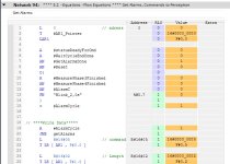
stl-code.jpg
 
Hi!

Try 2 more brackets, like this:

O(
A
A
A
)
O(
A
A
A
)
=
Kalle

...this reminds me of 'OA hela natten, OA hela dan'


And also move the FN beneath the last bracket.

Or you could use an intermediate bit after the first lines and the second lines, and then OR them.
 
Last edited:
I think the FN is configured wrong. It compares the current state of the RLO with the value of the tag included. If RLO = 0 and tag = 1, then the value is true. After this, it stores the RLO in the tag you included.

It is trying to store the current RLO value as in the memory bit assigned to the clock bit, which the PLC is immediately overwriting with the actual clock bit value. Since the clock bit is on 50% of the time, the FN will be true 50% of the time, if the logic before it is false.

What you probably want is something like:

A Blink 2.0s
FN Blink 2.0 edge bit
A MeasurePhase3Finished
AN MeasurePhase4Finished
AN AlarmC

You will need to create a tag that the FN will use to store the value. This tag could be in Global M memory, in a global data block or in the instance DB, but it could NOT be in local/temp memory. The value needs to be remembered for the next scan.
 
Thanks Kalle!!

"Skikkelig hygelig" should be the approporiate norwegian word?
Will try this out tomorrow.

mk42

If i understand you correct, and please correct me if i´m wrong:

<code>

A "blink 2.0"
FN "blink edge"

</code>

blink 2.0 gets read and saves the NTRIG in "blink edge".
"blink edge" can then be used as a negative pulse trigger?

In general, does the most of the bit operations begin with:

<code>
A "VAR"
FNC "COIL"
</code>

Is there an easy way to tell how the operands is execued in STL?
Since i did these two mistakes, i was clueless on why it didn´t work as i wanted to.
More trial and error or turning to you guys for help....


I´m more used to graphical presentation in general or SCL for text reprenation as my prefered languages, but it seems like I need to learn STL as well.... =/
 
Last edited:
If i understand you correct, and please correct me if i´m wrong:

<code>

A "blink 2.0"
FN "blink edge"

</code>

blink 2.0 gets read and saves the NTRIG in "blink edge".
"blink edge" can then be used as a negative pulse trigger?

I think you're close, but you might not be quite right. The blink edge bit is used only to store the value of the RLO from last time, so it can perform the edge check. The actual ntrig/fn result is pushed back to the RLO. You shouldn't ever use that edge bit again in your program.

In general, does the most of the bit operations begin with:

<code>
A "VAR"
FNC "COIL"
</code>

Not sure what you're asking here. A basic network with a contact followed by a coil would look something like

A "var"
= "Coil"

Is there an easy way to tell how the operands is execued in STL?
Since i did these two mistakes, i was clueless on why it didn´t work as i wanted to.
More trial and error or turning to you guys for help....

I´m more used to graphical presentation in general or SCL for text reprenation as my prefered languages, but it seems like I need to learn STL as well.... =/

If you're using an S7-300 or 400, one of the easiest way to find out how to write functional STL code is to write it in ladder and then change the view to STL. It isn't necessarily optimized; it will have lots of Nop, BLD, etc to ensure that the code gets formatted correctly if you switch back to ladder. However, for something basic like n_trig/FN, it will translate the code for you, and you can see how different instructions translate over. All FBD and LAD translates to STL, however, it is very hard to write STL that translates back.

Note that this doesn't work on a 1500, only the older platforms. If you're using a 1500, I would recommend avoiding STL altogether. Well, on any platform I'd avoid STL if possible, the difference is that on a 300 sometimes its the only choice. In a 1500 there is almost always a better way to code something than STL.
 

Similar Topics

I am a newbie to Macros and am looking for a crash course: I have an exisiting application running CompactLogix and using a panelview plus to...
Replies
1
Views
3,371
A couple months ago we had a little siemens I/O module go out and in the process of replacing it with one with a different rev level it ended up...
Replies
16
Views
5,525
Just wondered if anybody had any good videos (in english) of starting out with eplan p8 electrical?? Got to do a crash course, but don't really...
Replies
7
Views
6,776
Hello. In my last post I wished everyone good bye. I planned to retire and spend time with my hobbies. Ha ha!! It is difficult to make...
Replies
5
Views
4,095
Nope, I'm not giving one, I'm hoping someone else will. ;) I have LOTS of experience with RSLogix 500 and the processors that go with it...
Replies
5
Views
5,159
Back
Top Bottom