Closed loop control of liquid through a Solenoid Valve

This is the way I would do it. See Very rough diagram.
Set flow counters to zero, open both water & oil valves dose in fluids until set points reached.
In the mean time when a small level in tank, divert valve back to tank & run blender. Continue blending back into tank until mix is well blended, when batch required, open divert to sump & discharge.

What I get from your schematic is that if you're going for a 1% solution in 100 Litres, you would add 1 Litre lube with 99 Litre water through regular Solenoid Valves with a Flow sensor/meter and let both these liquids enter a tank. The tank has an solenoid valve for discharge.

You have a Static Mixer and a 3-way valve downstream of the tank, with one line going towards output to the sump, and one to return the liquid back to the tank.

A pump recirculates liquid from the tank through the Mixer and back into the tank for a set amount of time. This mixed liquid is then fed to the sump through the other port on the 3-way valve.

Questions :-
1. If I need to charge an entire CNC sump, the size of this pre-mix tank would be too large and thus the size of my Dispensing Unit.
2. Why is there a need to make multiple passes through the blender for the two liquids to mix?
3. How does this offer an advantage over an Inline mixing?
 
Ok, see what you mean. I don't know if the cost of a batch tank is greater than modulating valves but if not then maybe the process above would do the job. It only requires the flow sensors, shut off valves & divert valves and will give you repeatable results, the only thing you need to do is the maths to convert the pulses into litres/galls or what ever.
If you used say a Mitsubishi FX3U PLC this is reasonable low cost, has high speed inputs & floating point maths to do the calculations.
 
If I have to have a Batch mixing tank, I'll just attach a shear mixer or a mechanical stirrer to it. This really would have been too easy to achieve.

But my problem is that I am going for something that is compact and can be fitted if possible on each CNC sump. Cost is a major deciding factor here along with the compactness of the equipment.

Could you please go through the Lynch catalog of PWM drivers and tell me if I can use those seamlessly with a PWM Solenoid Valve without any need for adjustments or tuning. A PLC will definitely be used.

I am well aware of the Mitsubishi line of PLCs. Selecting a PLC will not really be an issue once I have the specs finalized.
 
It doesn't The way I look at it is that to get a good mix when the oil & water enter the tank they will separate, using the mixer/blender to mix the solution back to the tank makes sense if using a tank to batch or you may get water before oil. The only way to blend in-line is to control both the oil & water at the same time i.e. injecting it into the mixer. As I say if you wish to go that way then you need to work out the flow rates to control both liquids at a 100-1 ratio because if the oil finished some time before the water then the final bit through the blender would be water. maybe not a problem a slug of water entering the CNC sump as it may well mix but you have stated that it may cause problems.
If you had adjustable manual valves on each leg you could set them so approximately a 100-1 ratio of water & oil feed at those rates & just count the pulses, hopefully, if the flow variance is not too great then the two dosing systems will finish at the same time.

Yes the last part is what I will go for, seems like. since you're from the UK, you may check out Oracle from Jemtech for reference of what I am going for.

Also, the chemical doesn't really float on water like a neat oil would. Have a look at this - https://www.quakerchem.com/product-lines/metal-removal-fluids/

Tt mixes quite fast.
 
Right, the more information you give us the better, I was unaware that this would be on each CNC, without all relevant information I had to assume this was a system feeding a number of CNC's. in that case if using pulse units without a flow rate then you will either have to convert the pulses into a flow rate. then use this to control your valves. To get a reasonable flow rate from pulses you will have to sample the pulses over a time period for example count the pulses over 5 seconds and work out the flow rate based on the "K" factor given for the flow sensor. for example if the "K" factor is 1000 pulses per litre and in 5 second sample you get 5000 pulses then it would be a flow rate of 1 litre per second. however, the shorter the sample time the less accurate it will be on the other hand sampling over a greater time the slower the response will be. you need to find a reasonable compromise. I am not familiar with those controllers but have used similar ones i.e. motor controlled positioners so there should be no problem.
 
So here's the thing. Fitting one on each machine is the ideal case. At the same time I am also preparing myself for making one Unit suitable for a number of CNCs.

So if I have to use a pump for the coolant(or lube), which type of pump would you suggest?

Another thought, if at all I decide to pull the coolant straight from a drum (instead of having a tank), how would you suggest i do that?
 
I am no expert on pumps, only what I have learned from many commissioning jobs, I leave that up to the process experts I only design the controls & software around the mechanical equipment. If I have to come up with a design I call in the reps to do the calculations on pipe size/ flow rates and types of pumps & valves. All I can say from experience that use any type of pump suited for the medium for transport but for pumping in lines with flow meters it is better to steer clear of diaphragm or reciprocating pumps.
 
This is a way that I would approach the problem giving what you seem to have, I would not control the water automatically just convert the pulses to a flow rate, do the maths to convert it into say litres/second, divide it by your ratio i.e. 100-1 to give you the required flow rate of the oil. use this as a set point to control the oil valve.
So:
sample both flow pulses to give you actual flow for both products.
Convert them into meaningful values, divide the water flow rate by the ratio of oil to water, use that as the set point to drive the oil valve.
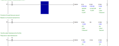
The theory is that if the water rate changes the required rate for oil will also change, using this to modulate the oil valve seems pretty simple to me. In practice may be a little harder but achievable It is very difficult to simulate in a real world but I have done a little code attached, This is just to get the flow rate of the water and the required flow rate of the oil, you would also need to accumulate the pulses every 5 seconds (or what ever your sample rate is) so that you can compare the water amount to the total value you need. Shown is a simple ladder (I would have done it with less rungs but for clarity I have split it, however, I probably would have written it in FBD rather than ladder.

Flow.png
 

Attachments

  • Flow1.pdf
    71.5 KB · Views: 6
This is a way that I would approach the problem giving what you seem to have, I would not control the water automatically just convert the pulses to a flow rate, do the maths to convert it into say litres/second, divide it by your ratio i.e. 100-1 to give you the required flow rate of the oil. use this as a set point to control the oil valve.
So:
sample both flow pulses to give you actual flow for both products.
Convert them into meaningful values, divide the water flow rate by the ratio of oil to water, use that as the set point to drive the oil valve.
The theory is that if the water rate changes the required rate for oil will also change, using this to modulate the oil valve seems pretty simple to me. In practice may be a little harder but achievable It is very difficult to simulate in a real world but I have done a little code attached, This is just to get the flow rate of the water and the required flow rate of the oil, you would also need to accumulate the pulses every 5 seconds (or what ever your sample rate is) so that you can compare the water amount to the total value you need. Shown is a simple ladder (I would have done it with less rungs but for clarity I have split it, however, I probably would have written it in FBD rather than ladder.

Thank you so much for that. I am going to talk to my PLC Engineer. I have understood what the concept that you've described. Now my next quest is to find a suitable PWM Driver for the proportional valve.

Any specific specs that I should ask for in the PLC?

Can't thank you enough for all the help you've offered so far.
 
So if I have to use a pump for the coolant(or lube), which type of pump would you suggest?

My favorite brand is Prominent. Be sure to size it for a flow rate that will more than cover the highest flow rate required, and be aware that they are typically spec'd in litres or gallons per hour (not minute).

You will get what you pay for. Our water customers buy the cheap stuff, and they end up with a graveyard of them (LMI, Wallchem), but they are usually dosing very harsh chemicals (sodium hypochlorite, caustic soda, hydrochloric acid, etc). The LMI and Wallchem pumps hold up well with milder chemicals.
 

Similar Topics

So it looks like i am stuck with an old reliance DC drive on this project instead of the powerflex dc w/ 22-COMM-E. That being said i am trying to...
Replies
0
Views
1,189
I have just received a RFQ for a closed loop pumping system (hydroforming ). I did a small system like this about 8 years ago in a SLC. It worked...
Replies
3
Views
2,304
Is it possible to operate a unidrive sp in closed loop vector contol to drive a roller that is turning in a cradle type configuration and the...
Replies
2
Views
2,001
Hey guys, Im not sure how appropriate this is for this forum but I have received alot of help from you guys in the past. Im taking industrial...
Replies
4
Views
2,163
HI, i am trying to control DC motor and encoder,by using plc200.cpu222 HSC 0,and analog output card. can you help me by giving me a hint about the...
Replies
2
Views
1,956
Back
Top Bottom