Carpet Accumulator Control

JohnDruzianic

Member
Join Date
Mar 2007
Location
Auckland
Posts
9
Brief Process Description:
Carpet leaves an oven (at approx 2 metres/minute), is pulled into an Accumulator by an Entry Roller. It is pulled out of the
Accumulator by an Exit Roller. From the Exit Roller it spills into a "J Bin". Downstream from the J Bin the carpet is rolled up into carpet rolls for dispatch using the Roll Up Roller.
Carpet travel through the oven must not stop. If carpet is not being rolled up, it will build up in the Accumulator.
The Accumulator comprises two pairs of parallel horizontal beams. Horizontal rollers are fixed between each pair of beams.
Carpet is threaded between the rollers in a zig-zag. The top pair of beams is fixed. The bottom pair of beams will float as the carpet builds up in, or is pulled out of the Accumulator.

The purpose is to control the speed of the Accumulator Exit Roller. A pair of PID instructions will be used.
One for Coarse speed control and one for fine speed control.
The coarse speed is determined by either the Roll Up roller (if carpet is being rolled up) or the Entry Roller (if carpet is not being rolled up and the Accumulator is sitting on the bottom springs). If the Roll Up roller is stopped and the Accumulator is lifted off the bottom springs, the Exit Roller remains stopped and carpet builds up in the Accumulator until the Accumulator bottom beam rests on the bottom
springs. Then the Exit Roller starts at the same speed as the Entry Roller.

If carpet is being rolled up, the height of the carpet web above the J_Bin is measured and the
Exit Roller speed is adjusted to maintain the height of the web at a set value using the fine PID.

If the speed of the Entry Roller is used for coarse control of the Exit Roller, the speed of the Exit Roller is finely adjusted by measuring the sag of the carpet underneath the first incoming roller of the Accumulator and maintaining that sag using the fine PID.

The Problem:
My problem is that the Exit Roller (in order to keep up with the Roll Up roller) will have to lift
the combined mass of the carpet and the bottom pair of beams (and rollers). At that stage the dymnamics are different
from when the Accumulator bottom beams are resting on the bottom springs.

Should I use the same pair of PID instructions regardless and have the PLC (Schneider Twido) change the Kp, Ki and Kd values
depending on whether the Acuumulator is resting on the bottom springs or has been lifted off the bottom springs ?
OR
Have a separate pair of PID instructions (which have their Kp, Ki and Kd values fixed) to take over control when the Accumulator is lifted of the bottom springs. The non-active pair of PID instructions are set to manual mode and they track the active pair so that bumpless transfer can occur.
 
I would switch in the new gains as opposed to switching between the controllers unless the nature of the controller changes. For example, if one of them is reverse acting and the other is not the two controllers will work best.

I'm a bit confused by the accumulator action, however. It sounds to me like the accumulator is non-driven and its position is simply the result of the feed differential between the entry and exit rolls. The accumulator is really needed to take up material during the roll change event. So during normal run the accummulator should be in it's minimum accumulation position. Given your physical description that would put the bottom rollers near their upper travel limit. However you don't tell us how you get the accumulator roll back to the minimum accumulation position.

You indicate the exit roll will use either the speed of the entry roll or the speed of the roll-up as its "master" reference and is further trimmed from there. You also indicate that during roll-up the exit roll us being trimmed by the material height in the J-Bin. Unless you are using the accumulator position to regulate the roll-up speed the system is ignoring the web span between the entry and exit rolls during normal run. This isn't so good.


Also, make sure you understand the dynamics of your system and why things are changing. Unless I misread your description (which was very detailed, by the way; well done) you are trimming a velocity command to the exit roll in both cases. Your system gain isn't chaning because of the load on the exit roll motor (increased weight). It is changing because a change of 0.1 meter/min of exit roll tangential speed is not producing the same change in the measured variable (either J-Bin carpet height or accumulator entry web sag). The change in exit roll load needs to be accounted for by drive velocity loop tuning. That is to say the drive needs to be able to apply more torque per RPM of speed error when the accumulator is in play. However, I doubt you will need to do this given the gearing you mush have. I just bring this up to get you thinking a little more about what your actual process variable is and what your PID output is actually doing to it.

Keith
 
It would be nice to have a drawing or picture. I am familiar with accumulators like they have in steel mills. I was following when you said the accumulators are horizontal. I would expect the rollers to separate or increase the distance between them to accumulate more carpet but then you mentioned floating and springs. Another possibility is that the horizontal beams swing and aren't always horizontal. This creates vertical space between the rolls that accumulates material. This is where a picture would be nice.

Having two PIDs control the same thing is asking for trouble. They will 'fight' each other. I agree with Keith, there can be only one PID and some sort of gain scheduling is necessary.

I believe in using feed forwards as much as possible.
 
Peter, his accumulator is what you are talking about with the horizontal accumulator, just turned 90 degrees. His moving portion of the accumulator moves up and down to provide storage. When he was talking about the horizontal beams he was referring to the frame holding the rolls. From what I can tell the accumulator in not driven so the carpet will move the accumulator if the entry roll and exit roll speeds are different. We build quite a few of these so I have a pretty solid picture in my head of what he is talking about.

I think he is using speed feed forward based on his description. If the accumulator is in its active area of travel the roll-up speed is the exit roll speed basis with a PID trim based on the J-Bin material height. If he runs out of accumulation (the accumulator is on the springs) he uses the entry roll speed as the exit roll speed basis with a PID trim based on the material loop coming out of the entry roll and into the accumulator. At that point the J-Bin is just filling up more than it would normally be.

I am writing this as much for JohnDruzianic as anyone else. This is how I interpret his post. If this is not the way this thing works he has to tell us how it is different if he needs more help.

Keith
 
"Peter, his accumulator is what you are talking about with the horizontal accumulator, just turned 90 degrees"
....That is correct.
"His moving portion of the accumulator moves up and down to provide storage. When he was talking about the horizontal beams he was referring to the frame holding the roll"
.... The top pair of horizontal beams is fixed. The bottom pair of horizontal beams can rise as carpet is pulled out by the Exit Roller. If the Exit Roller stops (because Roll Up has stopped), then the bottom pair of horizontal beams will descend as carpet flows into the Accumulator. There are vertical rails that prevent sideways motion of the bottom beam. There is a mechanical system to ensure that the Bottom pair of beams remains parallel to the top pair of beams. Idler rollers (in horizontal plane) are supported between each pair of beams. The carpet threads through the rollers. Steel mill Accumulator turned through 90 deg is apt.
 
Im missing something, is the accumulator counter weighted?
When the exit roll stops the accumulator must accumulate or go up right?
What senses the position of the accumulator?
I've done these too, like Peter said- Any chance of a sketch?
Why have a J Bin (I call it a J scray) after the accumulator?
The accumulator is suppose to keep tension on the material and keep it from wrinkle when the winder stops and the process keeps running.
 
Originally posted by PLC:
When the exit roll stops the accumulator must accumulate or go up right?

Actually it accumulates down. His stationary rolls are on top.

Originally posted by PLC:
What senses the position of the accumulator?

That's a good question. It kind of decides the options he has.

Originally posted by PLC:
Why have a J Bin (I call it a J scray) after the accumulator?

I would suspect they want to pull material out at a tension less than what the accumulator (in its present configuration) can provide. We have customers that ask for this occasionally.

Originally posted by PLC:
The accumulator is suppose to keep tension on the material and keep it from wrinkle when the winder stops and the process keeps running.

I didn't think carpet would do that. It has some pretty good cross-machine stiffness.

Keith
 
"Im missing something, is the accumulator counter weighted?" No

"When the exit roll stops the accumulator must accumulate or go up right?" No.The Accumulator bottom beam goes down as carpet enters it via the Entry Roller. When the Accumulator bottom beam hits the bottom limit switch, the Exit Roller starts again.

"What senses the position of the accumulator?" Top Limit Switch and Bottom Limit Switch.

"I've done these too, like Peter said- Any chance of a sketch?" Can send a video.
Why have a J Bin (I call it a J scray) after the accumulator?
The accumulator is suppose to keep tension on the material and keep it from wrinkle when the winder stops and the process keeps running.
 
Put a position sensor on the moving carriage and control
It like a large dancer
Done
 
I am confused,
You are are talking about controlling Speeds and Lengths and then you are talking about dynamics of lifting the Accumulator from the bottom limit
which is a Load or torque requirement on the roller - If you cannot control speed then the sizing of the motor needs looking at.

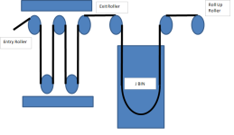
If the following diagram is right
Carpet.png

Then you have a SPEED controller on the Exit Roll
Where the speed reference of the exit Roll
Maximum of
Entry Roll Speed if Accumulator on bottom stop
J BIN level PID with a speed feedforward from the Roll up Roller speed
Plus the Roll up Roller Speed when the Accumulator is at the Top stop must be limited - eg cannot go faster than entry roller
 
In all of my experiences with accumulators, the accumulators were never allowed to come to rest on "bottom springs" when the accumulator is full. The web (material) would lose all tension when this happens - typically very undesirable.

We always have a position sensor on the accumulator. When the accumulator is 98% full, the exit roller runs that same speed as the entry roller with trim from a PID loop to maintain the accumulator at the 98% level. If the accumulator is above 95%, then the exit roller can run any speed that you desire.
 
Hopefully MichaelG's drawing is accurate

I like the drawing.

It is clear that the exit roller has two things 'tugging' on it. The accumulator will turn the exit roll counter clockwise and the carpet in the j bin will turn the exit roll counter clockwise.

The difference between the two torques can be a bias if the exit roll is controlled in torque mode.

Torques can be measured impirically and a table or equation for bias generated. I had to do something like this for a rotary shear once. The motor had to over come the torque due to gravity. A sin() function did the trick and the bias was added to the control output. This trick wouldn't have worked if the drive was configured in voltage or velocity mode.
 
John,

As I understand it, your exit roll is in speed control; so long as the motor / gearing is well sized then I doubt that the I and D parts will be required as the dynamic requirements of the system sound minimal.

A P&ID of the system would be really useful, many members of this forum are familiar with accumulator, winders and the like. A few things are still unclear; is the purpose of the accumulator to store carpet during roll change or is it to provide sufficient capacity for the reel up? In other words, is the accumulator normally full of carpet or empty?

Nick
 
In other words, is the accumulator normally full of carpet or empty?
Yes, that is what I was getting at.
The more material in the j bin the more the carpet will pull clockwise.
The more material in the accumulator the more the carpet will pull counter clockwise.
Calculate a net pull and use that for a torque offset or bias.
Use the any other roll speed information for feed forwards or gearing references.

I don't see where the tuning should be that critical where a PID won't do the trick.

I see the main problem as being one of deteriming the speed reference for exit roll. If the accumulator is full the exit roll must start rotating faster but what if the j bin is full? Not good.
 
Last edited:
I have been following this thread with interest, mainly because I am also in the carpet business. Theoretically I should not be answering to this thread as JohnDruzianic (who looks like he has bailed out on the thread) is competition to us, but i will give some pointers.

MichaelG, your picture is basically what we have, our accumulators have 10 loops though, and three accumulators, each about 20metres high, each roller is servo driven (trick one). But the main trick to acummulator control is using loadcells, one loadcell per accumulator, this basically allows you to control the following motor.

I really dont see the need for the Jbin, if your accumulators are big enough, rollup direct out of the accumulator. Our accumulators can hold up to 3Km's of carpet, thats more than enough time to do a core change, and we are running our line a hell of a lot faster. The operators keep the accumulators as empty as possible, just enough for the rollup to roll the disired length

JohnDruzianic, pm me, I can put you onto the OEM that built ours, they are in Belgium
 
Last edited:

Similar Topics

How is floating web accumulator works ? I have a project where I will control a floating accumulator without speed trim. Input and Output rolls...
Replies
14
Views
3,530
Hi All, E+H Promag W 500, 5W5B1H (Ethernet I/P implicit messaging 500ms) AB 5069-L330ER v33.01* I have a customer requirement where I need to...
Replies
2
Views
1,405
Greetings all. I was hoping that some one that uses connected components by AB can help me with programming a accumulator reset in my program. I...
Replies
0
Views
4,720
I have a program that runs a CPM Pelletizer. It has shear pins that break when rocks or other debris lodge in between the rollers and die. When...
Replies
2
Views
1,501
Hi, I was trying to read counter accumulator from ML1400 i.e. C5:0.ACC on FTView SE on ethernet. I am able to read many other counter...
Replies
3
Views
2,222
Back
Top Bottom