Split range control with action variables of logic type

Steven01

Member
Join Date
Oct 2015
Location
Prague
Posts
25
Hello,

I have following control task. I have to limit a current drawn from a source of power in a grid where I have following power consumptions:
  1. battery charger
  2. variable frequency drive
  3. aux power consumption 1
  4. aux power consumption 2

The current drawn from the source of power can be limited via these action variables:
  1. lowering the charging current setpoit for the battery charger
  2. lowering the torque setpoint for the variable frequency drive
  3. activating the logic input of the aux power consumption 1 for turning the consumption off
  4. activating the logic input of the aux power consumption 2 for turning the consumption off
(the action variables above are ordered according to their priorities)

I have been thinking about the control structure suitable for this control task. It seems to me that the so called split range control could be a solution (at least as far as the first two action variables). The problem which I have regards the last two action variables. I am not sure how to integrate them
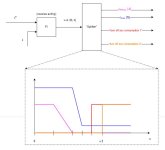
organically into the split range control structure. The idea which I have is depicted on the attached figure.

i.e. the logic signals are simply activated based on the value of the output of the PI controller in the same manner as the charging current setpoint and torque setpoint. I am not sure whether this approach can work in practice. Does anybody know a better approach for integration of action variables of logic type into split range control structure? Thanks in advance for any suggestions.
Split_range.JPG
 
Thank you for your reaction. As I have mentioned in my question. The priorities are according to their position in the list of the action variables.
 
And the power on each? Systems I've seen like this (Power Management for ships), you'd have for each consumer a priority and a minimum required that you can't go under. There were various alarms as well related to breaking any of these limits to ensure operation.


So in operation, you take your lowest priority down to meet your available power. If the drop reaches the minimum limit, you then calculate the difference and remove from the second lowest priority and so on.


You do have to be careful with your "digital" consumers and ramp the available power towards the "analog" consumers to reduce spikes in the network and also the possibility of instability as it can happen that power that was available, suddenly isn't anymore.
 
Is 4 the highest priority i.e. the last one to be kept running when the others cannot run due to the total current limit? Or is 1 the highest priority?


Do we know the maximum current draw of each consumer ahead of time?

Are the aux power consumptions fixed, or at least known at any time they may be started?

How do we receive (determine?) the total current limit?
 
How quickly do the consumptions need to be reduced if the total current limit drops?

How frequently is it allowed to change either of the binary (last two) action variables?
 
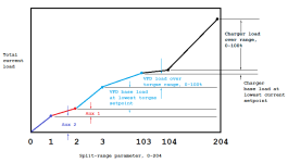
If you can predict the loads, you can make the plot below (assumes priority 4, aux 2, is highest priority); I think this essentially the same thing that @cardosocea is suggesting.

Then it is a matter of finding the greatest value of the split-range parameter, SRP, that gives a current less than or equal to the current limit, which can be done with 8 steps of a binary search.


Then,

  • If SRP > 0, turn on aux 2
  • If SRP > 1, turn on aux 1
  • If SRP > 2, run VFD torque at (SRP-3)% of range
  • If SRP > 103, run charger current at (SRP-104)% of range
Depending on relative magnitude of the actual loads, it may be possible to run some or all of the VFD and charger if the limit is not enough to run either Aux 1 or (Aux 1 + Aux 2). Once that condition was detected, a similar plot without one or both of the aux loads could be implemented.
Untitled.png
 
This problem is not really one for a PLC alone. The way most experts would use is to define a cost function then find how to minimize it. For instance, each of those 4 items must have an ideal set point or value. The idea is to minimize a weighted sum of squared errors between each of the actual values and their set point. In control theory Q is used for the weights and J is the cost function so
J(SP[], PV[]) = Q[0]*(SP[0]-PV[0])^2+Q[1]*(SP[1]-PV[1])^2+Q[2]*(SP[2]-PV[2])^2+Q[3]*(SP[3]-PV[3])^2
So given an array of set points, what values in array PV minimize J?
First you need to define the cost function by defining the weights in the Q array. Then you must have a function that will find the minimum cost, then the "spliter" most attempt to control the 4 values in the PV array.
Finding the minimum could be done on a PLC but it would be best if a PC did this and downloaded the values to the PLC.

There was a recent thread about PID control / finding the model. The same algorithms could be used here. An algorithm called Nelder-Mead AKA "Ameoba" is simple enough to implement in ST but the algorithm will require a lot of CPU power so it is best down on a PC with the set points down loaded to the PLC. The algorithm is found in Numerical Recipes in C but it can be found easily on the internet.

The sum of squared errors is often used as a cost function because it doesn't care if the errors are positive or negative after squaring, the sums are always positive. Derivatives that find the slope that go "downhill" to a smaller cost ( J ) are easy to calculate.

Learning how to define and minimize cost functions is worth while but it isn't a PLC topic.
 
Given the priorities provided by OP, each Q[N]/Q[N+1] ratio is basically ∞, so this is a (mostly discrete) PLC problem after all.
 
The first two items are variable. Actually, the "discrete" items will be variable too if they get a fixed on/off percentage from the PI output since the output will change.
Anyway, if you want to know how the big boys do it, that is it.
The real problem is defining "what is optimal?" That really is the trick. I have seen people discuss linear quadratic control where they same to ignore the art of picking the weights. There was a recent thread where someone claimed to have a Kalman based temperature control. There was a q and r value in that too where q is the weight for the process error and r the weight for the measurement error.
I will now sit back with my pop corn and watch.
 
As far as the priorities of the action variables. The action variables above are ordered according to their priorities, where the first one has the highest priority i.e. this action variable is the action variable of the first choice and the others are activated only in case the influence of their predecesor isn't sufficient.
 
I think that the possible solution could be to let the split range controller produce only:

1. charging current setpoint
2. torque setpoint

The logic signals for turning the auxiliary consumptions off will be produced by two hysteresis controllers. Those controllers will be enabled only in case the split range controller has both of its outputs at their lower limits.
 

Similar Topics

Hi all, I have an application which requires a split range controller for maintaining a level in a tank via 2 control valves. The AB platform...
Replies
5
Views
2,122
Hello everyone, I am currently working on my senior capstone project, I'm having trouble trying to figure out how to set up a split range control...
Replies
5
Views
3,098
Hi there, I have to control a temperature (at the outlet of a two stage heat exchanger) with two different heating water lines; 65°C and 95°C...
Replies
4
Views
3,654
hey all, I am struggling with a problem here and out of ideas on how else to achieve the desired result. I have a monitor inside a machine with...
Replies
0
Views
121
Hello everyone. I have an PLC L35 (fmw 16) with address 192.168.1.1 and too many connected ethernet devices (3 hmi, a lot of ethernet port, asi...
Replies
11
Views
740
Back
Top Bottom