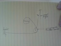
Uncoiler payout programming

I wonder if there is some contingency in the tray accumulation model, and over the course of a shift there is more material put in the tray than calculated by the model, because erring slightly on the side of extra in the tray does not cause an operational problem, while erring in the other direction would be a problem. Then at the end of a shift the extra material is dealt with manually.

P.S. to the OP: thanks for posting those images
 
I just went back and reviewed the video to see if I may have missed something
And yes I did
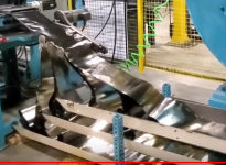
That’s not just 1 web and unwinder but 3 web’s and 3 unwinders
That helps explain the mess of material under the intake
Each web had it’s own roller table to carry the web material to the machine
This explains the 3 rollers on intake and the osculating motion on the input table .
And the general accumulation of web material on the floor.
In addition the unwind has pneumatic brake to stop the unwind
If you look closely there is a pressure regulator on left side of the unwinder
It looks like the brake is not working on any of the unwinders
From what I see it looks like the unwinder is set to run a short pulse when the machine input is advancing to unload a small amount of the web and then stop when the input feed stops and the brake should stop the unwind but with no brake it drifts and plays out to much material so the extra bulds up and accumulates on the floor and the roller table. It looks like there is system to measure the diameter of material on the roll to set the unwind speed but it is only on the first station. It should have one on all stations.
The web going into the machine is 3 layers deep
We really need to see more information on the machine the more information we have the better we can help you
What does that machine actually do, the web material looks like it’s mylar foil of some kind
 
One thing that really stood out is the sudden snatch when the accumulator table is short of material, I worked on something similar many years ago, the obvious answer is to put dancing rollers on each feed, use a photocell to detect when the dancing rollers tighten (hard to explain), but it will also depend on if what ever takes the material is capable of pulling against a slight resistance when the material hits the dancing wheel. we used this on cellulose wadding (like toilet paper) so it was delicate but worked a treat.
There are many ways to produce a dancing arm (s), for example a simple one or perhaps two where they travel vertical, hit a sensor and that feeds more material.
The one I did had an inverter that ran at a given speed (set by the operator depending on the feed length) then if the dancing roller moved up (web tightening) then this triggered a PEC that increased the feed speed for a pre-set period to drop the dancing roller, on one machine we had a fixed roller and a dancing one & on another we had two fixed & two dancing.
Originally, the material feed was adjusted to feed at a given rate but this proved difficult to control, sometimes it would tighten & break or pull the material back so loose registration or over time feed too much & the folds would also cause pull on the material loosing registration.
 
This is turning into a great thread. Thank you guys for contributing.

I'm going to try to catch up here all at once.

Drbitboy, you are correct. The trays are set up to overfeed. As you have stated previously, there is an accumulation of error. The operators can use a push button to skip up to 5 feeds to use up excess material in the trays while it's running. If left unchecked the operators will have to manually deal with extra material 2-3 times per coil. Also, there are 5 sheets per coil and 3 coils feeding the cutting section.

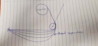
GaryS I do think the loop is the best way to go however there are a few challenges. Having 5 sheets per coil leads to sheet separation as the material is uncoiled. The outer sheet has a larger circumference than the inner sheets. This also causes an issue for any roller or dancer arm set up. In order to create a loop the uncoilers would have to be raised up which would make it to difficult for the operators to load or a pit would have to be installed which is too expensive.

It is messy but it does work. You're correct GaryS, there is a laser distance sensor that measures the circumference which offsets the speed as the coil gets smaller. The goal is to run the feeder as fast as possible with the highest accel. When too high, the sheets will tear and/or the feeder will jam. The speed and reaction time of the uncoiler is tuned for a wide range of feed lengths. When the feeds are small I'm able to increase the velocity and acc of the servo. Long feeds require more material in the trays and that's when the uncoilers have to keep feeding which is why they seem to be going too fast.

You are correct GaryS, there are 3 uncoilers. The oscillation is meant to relax and line up the sheets prior to and during entry into the feeder. There are no brakes. Stopping/starting the uncoilers would impact the cycle time too much.

Unfortunately, I can't reveal too much of the machine. We build these in-house and don't want competitors to see anything.

L D[AR2,P#0.0] The machine is working but the operator has to constantly monitor the trays. They have to skip feeds (stop the uncoiler for up to 5 feeds) or wait till there is too much material in the trays, then stop the machine and manually adjust the amount in the trays. This impacts cycle time. While the machine is running, the operator is assembling the product. I consider my programming skill to be at an intermediate level. Unfortunately, I have no mentor to learn from or discuss programming with and I'm finding that my development has slowed. I wanted to see how other programmers would approach this.

parky As mentioned above, sheet separation will prove difficult with dancer arms. They work well with continuous feed setups or slow intermittent feeds.

I do have an idea for trays that I'm going to pitch. See pic. Thoughts?

Thanks again guys.
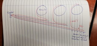
20210302_091722.jpg
 
Last edited:
Your unwinders shown in the diagram are opposite to the actual machine, will this make a difference, also as suggested, there seems to be no brake on them so they roll on, also looking at the video the feed seems to be rather fast but pulsed, even just tuning a bit i.e. feed longer but slower, also at the moment because of the feed speed too fast it seems to do multiple folds then those are pulled along causing snatching.
I think before using the sensors you need to tighten the feed speed closer to the main take up of the product. I do however think at least sensors to detect a single loop back will work but it will need some tuning.
Actually the machines I modified were not continuous feed it used to print & cut drip mats (coasters) so it was as per your machine, some of the original machines the coil drum was driven by a ratchet arm so the idea was the feed matched the press just like a ratchet drive forward stroke ratchet back the reciprocating arm driving the feed was adjustable on the flywheel so it could try & match the feed length of the press but if the operator did not keep an eye on it then eventually it would either tighten or gradually feed too much , the extra material would fold over a number of times causing the material to stretch & loose slight registration on multi colour print & cut. so even on those machines the dancing arm worked well, we had to design the dancing arm to have little pressure on the material or it too could cause mis-registration (the press had up to 3 colour prints plus a cut so each index put on a print colour & cut). We did another one where we had little space for accumulation here we just used two photocells, one lower than the other the idea was to keep a loop that was twice as long as the maximum feed, the lower PEC when cleared to when the upper was cleared created a value of x msecs, we used this to determine the feed time so when both PEC's were un-covered it fed a given length, this also worked well and only used standard motors with VFD's & DC injection braking.
EDIT: forgot to add, the bottom platen also reciprocated up & down so also gave the same effect of snatching i.e. feed & raise then lower so gave the same effect as your press or what ever it is.
 
Last edited:
I like that design. Sheet separation could be an issue though. It could work if there is enough room to accommodate the separation. As more of the coil unwinds the sheets separate more and more.

20210302_151726.jpg
 
I like that design. Sheet separation could be an issue though. It could work if there is enough room to accommodate the separation. As more of the coil unwinds the sheets separate more and more.


Yeah, I was wondering about that.


Maybe the dancer roll could be lifted over time (e.g. a shift), but then we're into serious Rube Goldberg/Heath-Robinson territory.


How is it handled with the current flat trays?
 
Currently, it just builds up in the trays until it becomes an issue, then the operators square it up and start again.

Had to look up your reference to Rube Goldberg/Heath-Robinson. That's a good one.
 

Similar Topics

Hello all. Anyone got experience or can share some knowledge on how to do this. I’ve got a new application where I am guiding metal strip from a...
Replies
19
Views
7,167
Dear all, I have fx2n plc on my hand but I don't have the programming cable sc-09 and it would not be easy for me to get one. I need the cable...
Replies
3
Views
110
Hi all, i am the new controls guy at the plant and i have inherited a pc from the previous controls guy with Siemens tia portal version 16 and 17...
Replies
20
Views
878
I need to pull the program off of an old 90-30 so I can convert it to Allen Bradley. This is my first time messing with GE and I don't have the...
Replies
2
Views
84
New to vfds. I put in parameters. IP, but I get ethernet flashing and link solid. What did I do wrong?
Replies
9
Views
473
Back
Top Bottom