Mapping Buffering Alias

JSch

Member
Join Date
Feb 2021
Location
Perth
Posts
7
Hi guys,

I am new to the forum and Rookie PLC Programmer. I did start programming a bit of RsLogix500, Studio 5000 and Step 7 V16 and still can't get my head completely around IO Mapping/Buffering/Alias

As far as I know (you correct me if I am wrong) you still do IO Mapping on RS Logix 500 and Studio 5000 but do you actually do this with Step 7 as well?
Is it good practice and every decent programmer does it?
Does it matter where exactly the IO Map sits in the program files tabs?
Is buffering the same as debouncing?

Any advice, links etc. are highly appreciated.

J

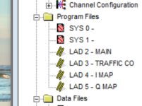
IO Map.png
 
Welcome to the forum!


Your screenshot is from RSLogix 500 software, and in that PLC there is no need to map the I/O. The PLC's that use the RSLogix 500 platform run a synchronous I/O update - that is, the PLC does:
Code:
Read inputs
Execute code
Write outputs
Repeat

However, the newer series of AB PLC's that use RSLogix Designer/Logix Designer run an asynchronous I/O update. That is, inputs and outputs are updated at a fixed rate, completely independent of the code being executed.

This can cause problems, because the state of an input could change partway through the program cycle. Imagine if you had two rungs of code, one that says "if input A is on, do this". Then two rungs later, you have a rung of code that says "if input A is not on, do that". It's possible that the status of input A could change between those two rungs, and then the PLC will either do both of those things, or neither of them, when you only wanted it to do one or the other. Depending on what those things are, that could have negative consequences.

So, to prevent this, most programmers map the physical I/O once each scan. That way, the status of the input can change partway through the code if it wants, but I won't update the internal state of that input until I've finished my program scan. I will read the input, execute all my code based on the status of that input at the time I scanned it, then set my outputs, then start again - basically mimicking the way the old PLC's used to work.


I couldn't say whether or not you have the same issue on Siemens PLC's - I don't have enough in depth experience with them to know whether they use asynchronous I/O updates or not. But the important thing to note is, it's not the software that determines whether this is necessary, it's the hardware. It's a matter of whether the PLC itself updates the I/O synchronously or asynchronously. In Allen-Bradley world, it just so happens that they updated the software and hardware at the same time, so as a general rule, there's no need to buffer I/O in RSLogix500, but there is in RSLogix 5000. But that's still not because of the software, it's because of the hardware that each of those software packages is used to program. So it's less "do I need to map I/O in Step7" and more "do I need to map I/O for this processor".

All that said, there are some good reasons to map I/O even if you don't have the asynchronous I/O problem. If you have a sensor short circuit and blow up an input, usually a maintenance technician will just replace the sensor and try to move it to a spare input. If your input is only used once in the code, in an input mapping routine, it's a moment's work to re-map it in the code. You might have the sensor status tag used dozens of times throughout your code, but as long as the physical input itself is only referenced once, you only have to change one rung of code.

On the other hand, if you have the input referenced directly each time, it'll be scattered through dozens of routines. It'll be much more time consuming to find it and update all the references, and you run a much higher risk of messing something up and accidentally pasting in a normally open when it should be a normally closed, and so on.

Plus, it just makes things a whole lot cleaner, and it's much easier for a maintenance tech to get a foothold into your code if they can trace a wire to an input, and then easily find that input because all your input are mapped one after the other in a routine labelled "Digital_Input_Mapping"
 
Hi guys,

Thanks for the quick and detailed response, this helps and explains a lot.

I do get the part that it is good practice and makes the whole program cleaner and easier to maintain but I still do have some questions.

If the program scans I/Os asynchronous (Studio 5000, Logix5000), the location of the I/O Map Routine in program files would be important. Would you put I/O Map be usually be after the Main Routine or after the 'Logic' Routine or last? Or did I miss something and this doesn't matter at all?

Btw., did some research on the Siemens PLC and the I/O Mapping is as far as I know just done to keep the program 'clean' and not out of necessity. They do Mapping though a bit different using Data Blocks.

J
 
It doesn't matter so much where you put it, as long as it's only done once per scan. And then you just have to be aware that your input status could change when you do it. So if you did the input image update in the middle of your program structure, you'd have to be aware that the input state in the latter half might be different to the input state in the former half. Common sense really tells you to do it at either the start or the end of your program sequence.

If it were RSLogix 500, I'd have input mapping first and output mapping last.

In Logix 5000/Designer, I tend to have an IO_Mapping program as the first program in the task. Then all of my actual control logic gets put into one or more programs below that. Within the IO_Mapping task, I'll have routines for reading inputs and then writing outputs, in that order. On a small system, I might just split it up between Digital In/Analog In/Digital Out/Analog Out. On a large system I might split up each of those further, and map digital inputs from each different I/O rack in their own routine. I also do comms mapping to/from other PLC's here as well - comms is just another source of input/output data.

Of course, this technically doesn't match what an old PLC used to do. The old PLC would read the inputs, execute the code, then write the outputs. When done this way, the PLC will read the inputs, then write the outputs, then execute the code. Most of the time, it doesn't really matter - all that happens is I read the inputs, and then update the outputs according to the results of the previous scan through the logic.

In some cases this might matter. If I were using a periodic task, executed every 100ms, there would be an inherent delay of up to 100ms between when the code says a motor should run, and when the output mapping routine is next run to actually turn it on. Even when running the continuous task there's that inherent delay, which will be whatever the effective period of the continuous task is. I've never found it to matter - if your application is so precise that a a delay of a few ms will upset things, you're probably solving the problem the wrong way already.
 
All nicely and concisely put ASF, well done for putting in the time and effort in starting an OZe off on the right foot.
Logically one would think putting the I/O mapping first up makes the most sense, as well as calling the mapping routine first up in the main routine as well (just in case people forget as we see in threads from time to time, the routine you write is never going to work if it isn't called in the main routine).
 
You bloody Legends :)

Thanks JeremyM, PLCnovice61 and especially ASF for time spent on this perfect explanation. There is a lot to grasp at the start, especially when trying to learn 2 different Systems at once but I did make a big step forward with your help!
 
Another good reason for mapping I/O including analogues is that if you have a processor (or even simulator), you can disable the calls to the I/O mapping blocks and simulate without the real I/O, some platforms allow you to address I/O even if it does not exist, however, some will not, also if no simulator then some will not allow you to force (or write) to inputs so by not calling the mapping you can use the mapped bits in some temporary blocks to simulate the process by setting or turning on/off the map bits, just delete or disable these blocks and enable the I/O mapping when commissioning.
Note: I often find it is easier to write simulation code in the PLC than use the facilities in a simulator.
 

Similar Topics

I have always used mapping to buffer IO to avoid random program hiccups caused by changing inputs in the middle of a program scan. Now I am doing...
Replies
8
Views
4,031
Hi everyone, Kind of new at this, so we recently upgraded our 1769-l32e to the newer 5069-L320erm, i converted the file over and Verify the...
Replies
8
Views
401
Hello Guys I have an 1756-L73S Controller with a Fanuc Robot mapped as follows: - In 1756-EN2TR Slot 2 the Fanuc Robot is defined as an...
Replies
5
Views
267
This has been on my mind for a while now, wondering if anyone here has any best practices or insights. I have been working with a plant that has...
Replies
8
Views
545
Hi long time out... I´m in a project now, that request to upgrade an old SLC to a new ControlLogix. Just the PLC. It is connected now to a...
Replies
5
Views
1,959
Back
Top Bottom