Micro heartbeat back to Controllogix

Earthscape

Member
Join Date
Sep 2011
Location
PNW
Posts
86
I am remotely reading and writing a Micro 1400 from a CL, and want to set up some sort of heart beat from the micro to the CL. Whats the best way to do this ? I was thinking a timer, or an always on bit from OTE and msg it to the CL, but I'm looking for ideas.

Thanks guys
 
Could you use the free running clock on the 1400 S:4?

Not sure about the 1400, but on the 1100 it is zero at entry into run and when in program mode. I think it is the same on the 1400. I'd read it's value periodically and compare the last value to ensure it has changed and also check that it is not zero. Perhaps trigger a counter in the event the clock gives you the same value twice so you can ensure it really has stopped. Maybe set your counter to two or three.

Shawn
 
I ended up using my msg write function to 'echo' across the local heartbeat. Repointed the HMI tag at it as it comes back in the read word. Seems to work fine. Any foreseeable issues the way I did it?
 
Typically a heartbeat means that there is a bit (or pair of bits) that changes states on a regular basis because: One controller always clears the bit when it is set (or makes the two bits equal), and the other controller always tries to set the bit when it is clear (or make the two bits opposite), so the bit changes states as fast as the two devices are programmed to communicate. If either controller sees the bit stay in the same state too long, comms have stopped, so there are at least a couple of timers involved as well.

Another method is to simply use a pair of counters. The counter gets incremented and sent along with the rest of the data, the CPU on the other end updates a value on its end and sends it back (it can increment its own value or simply make it equal, depending on whether or not you need to "make up" lost messages if one ever gets skipped).

Using incrementing values has the advantage of providing a great visual cue for how fast and how repeatable the comms are occurring. When this value stays the same (EQU to a stored copy) for a period of time, then comms have stopped.

If you logic does either of the above, and either controller can tell when the other one is offline then it is complete. Actually, as long as it meets your requirement in this application then it is complete. My description may give you some food for thought though.
 
Last edited:
What I do is run a counter in the distant processor triggered every second. MSG the value of the timer .ACC back to the mother-ship. In the CL processor, examine the value of the .ACC (that was messaged back) and as long as the value does not change, run a timer in the CL. The value in the CL timer's .ACC buffer is the number of seconds since your last successful communication. If it goes too long, sound an alarm. We also display the amount of time elapsed on SCADA so the operator knows how "fresh" the data really is.

When the counter in the distant processor gets close to 32000, reset it and start over. The actual number being sent to the the CL is not important. It needs only be different than the previous value received for this work properly.

Bill
 
OkiePC's heartbeat solution is the simplest, and cannot fail.

Some heartbeat solutions that use a timer to toggle a bit can, in certain circumstances, allow the "reading" processor to keep reading the same state of the bit.

Implemetation of OkiePC's solution is as follows

a. in PLC1
A B
----| |----------------------( )--

b. in PLC2
B' A'
----|/|----------------------( )--


where B' is read by PLC2 from B in PLC1
and A is read by PLC1 from A' in PLC2

In both PLCs, simply reset an unconditional timer with one-shots off both states of either of the bits. If the timer times out, the comms has stopped.


+-TON-------------+
-----------------------------|Tiner On Delay |-
|Timer Comms_Wdog|
|Preset 1000|
|Accum 0|
+-----------------+
A Ons_1
---| |----[ONS]---+---------------------(RES)----
A Ons_2 |
---|/|----{ONS]---+

 
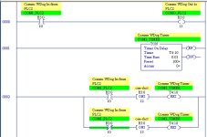
Using daba's example with a SLC, each OneShot instruction and RES instruction may require separate rungs.

Monitor the peak and average Comms_Wdog.ACC to determine the comms message rate if desired.
 
I should have said, monitor the trailing edge of the timer.EN, before the TON branch, and record the ACC each time it peaks before the timer is reset into a tag; call it "HeartBeatCycleActualmsec" or "HBmsLast" or something like that.

You can then, conditionally, take snapshots and record peaks from that value to get a sense of the communication stability and speed.
 
On the client-side device, I connect the normally open output of "message.ER" to a counter and preset the counter to an appropriate value, such as 60. When "counter.DN" is active, I run an FLL to zero out the result array to remove stale data. When "message.DN" indicates that the communication is back up and running, I reset the counter. This is assuming that you are using MSG commands.
 
Using daba's example with a SLC, each OneShot instruction and RES instruction may require separate rungs.

Yes, apologies, I forgot about the SLC ONS placement restriction.

Can be overcome as in the picture...

2011-11-17_073831.jpg
 

Similar Topics

I'm trying to devise a serial communications heartbeat for a GE Versamax micro IC200UAL006. Is there some internal system bit that I can examine...
Replies
3
Views
2,678
Hi, We couldn’t find anything specific, so am starting a new thread. I’m trying to migrate a config from a ML1400 to a micro820 & am experiencing...
Replies
1
Views
94
I’m running a micro 820 to measure a tank level, then turning on equipment at certain levels. I have an analog input (4-20) that I’m storing and...
Replies
10
Views
286
After updating a panel, I inherited another PLC for my "learning lab". It's a Modicon TSX Micro. I've not worked with a Modicon PLC yet, so I...
Replies
1
Views
139
Back
Top Bottom