0-10vdc simulator

lesmar96

Lifetime Supporting Member
Join Date
May 2017
Location
PA
Posts
520
I wanted to quickly test an 0-10Vdc analog input on a plc, but I did no have a professional simulator close by at the moment. So I thought I could rig it using a 24Vdc power supply and a potentiometer. But it just refuses to work. I have the positive from the power supply running into the positive of the potentiometer. The wiper of the pot then goes to the positive of the analog input. The negatives just go together. But the pot makes absolutely no difference in the voltage. It is a 1watt, 5K pot and either the whole way down or the whole way up, the output voltage on teh wiper terminal measures the exact same as the power supply voltage, maybe with a difference of 0.02volts. I figured teh output from the pot should be 0-24V. I checked the pot with my Fluke ohmmeter and I have a good scale of 0-5000 ohms on the pot.

Can anyone give me any suggestions of what I am doing wrong?
 
check analog input that you have voltage input wiring.
Current 500ohm internal resistor make voltage dividing different.

If you disconnect PLC input. Is there 0-24Volts on wiper.

It would be better if you use 5kohm pot and 7k ohm resistors on series, then you have 0-10V on pot's wiper.
 
depending on the resistance of your input you may have gone over 1W


I'm not sure right off the bat what the resistance of the input is but with the input disconnected and just the pot lying right on my bench. I still have 24V solid all the time on the wiper of the pot.
 
yes. that is correct. I was trying to think if that would make any difference, but I didn't think of any reason it wouldn't work to leave the 3rd pin empty.
 
the only thing I can think is your input resistance is so low the only thing acting as a load is your pot so it will have a constant voltage drop, I would put another resistor in series with it the other pot for instance cranked all the way over to 5K this should give you a 0-12V range
 
this thing is really getting the best of me. I just don't understand it and I know I have done this before.

Following the suggestion, I am now using a 9Volt battery rather than a 24VDC power supply. I take the positive of the battery and connect it to one terminal on the pot. The wiper of the pot goes to the red lead of my Fluke. The negative lead goes to the negative terminal of the battery. The plc inputs are totally out of teh question right now. I even tried a bunch of different pots. Switched to a 10k pot just for the anyhow. No matter what I try, the best I can get is about a 1V change. I know it is not my meter because I hooked up to the input and watched it in the plc software and that matches the voltmeter.
 
You have to put a load in series with the pot (light bulb or resistor) and complete the circuit. Then check voltage between the pot and load and that is where you can tap to the analog input.
 
I added another pot to get more resistance. Totally circuit resistance measured with my Fluke is 15ohms. My meter still reads just over 9V.
 
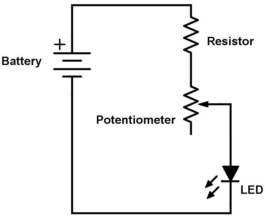
You need to connect the other leg of the pot to the negative of the power supply. To protect the analog input channel from overvoltage, put 7 Kohms of resistance between the plus terminal of the power supply and the pot. You should then see 0 - 10 volts on the wiper. Then connect the wiper to the PLC analog input. Also connect the negative of the power supply to the appropriate terminal on the PLC's analog input module.
 
Tried to find a quick diagram.

LED-Potentiometer.jpg
 

Similar Topics

i want to supply eight 0-10VDC inputs(variable) or 4-20mA current signals to my allen bradley PLC for testing purpose before giving it the real...
Replies
6
Views
3,094
Hello everyone, I don't have much of an electrical background and so I have these questions: Please check the attachments. I have 4 cases where a...
Replies
15
Views
4,168
Hey guys, I've only dealt with wiring 4-20mA analog inputs as the majority of instruments I've used are 4-20mA. I'm using a Mitsubishi VFD and...
Replies
1
Views
1,163
I have an actuator, Belimo cat.# AFB24-SR, that has 2...10VDC control input and feedback output signals. However, in their spec sheet, they say...
Replies
5
Views
6,377
I have a single +24VDC digital, non-high speed signal from a PLC that I need to feed into some monitoring equipment that is only rated at +10VDC...
Replies
16
Views
6,925
Back
Top Bottom