120 Motor Wiring Color

Tim Ganz

Member
Join Date
Dec 2010
Location
Dallas, Texas
Posts
689
I have an OEM machine that has their drawings showing several 1/4 HP motors using #12 THHN RED wire as the motor leads from the contactor.

I have always seen red as 120 volt control wiring not power leads for motors and they have T1 and T2 as red.

I wanted opinions on this if it would be best to change it to black as it has numbers of 6T1 and 6T2 or Black for 6T1 and White for 6T2.

Opinions?
 
For 120 volts AC power conductors, the various US codes and standards generally prefer black and white (if the white conductor is grounded).
 
Last edited:
I wouldn't switch the neutral, although it is allowed.

430.85: One pole of the controller shall be permitted to be placed in a permanently grounded conductor, provided the controller is designed so that the pole in the grounded conductor cannot be opened without simultaneously opening all conductors of the circuit.


I also wouldn't use a red wire for the neutral, but I don't know if code prohibits it though. I suspect your machine is available in 120V and 240V versions, and they just use the same color code for both. :confused:

🍻

-Eric
 
There is no enforceable code dictating wire colors, that is left to users. There are commonly accepted practices, but not following them is not unheard of. If you however had a specification requirement to your OEM, such as NFPA79, then they might be guilty of ignoring your requirements. Otherwise, it's just poor workmanship.
 
I am not sure of other codes but NFPA70 200.6(A) "Means of Identifying Grounded Conductors" (Neutral)

Says that "insulated grounded conductors (Neutral) of 6 AWG or smaller shall be identified by a continuous white or gray outer finish or by three continuous white stripes on other than green insulation along its entire length."

There are a few exceptions but none that fit what the OP describes.

We always used white for 120/240 volt Neutral.
And Gray for 277/480 Neutral.

BCS
 
Last edited:
There is no enforceable code dictating wire colors, that is left to users.
That is not exactly true if you are in the business of building electrical equipment. In addition to the National Electrical code requirement for the neutral and ground wire, what about the NEMA wire color standards (NEMA WD 1-1999)? If a NEMA standard is specified in an electrical equipment contract, it is as legally enforcable as any other part of the contract.


There are others such as the ICEA and TIA standards for multi-conductor cables. Many local electrical jurisdictions legally dictate wire colors that must be followed in that area.
http://www.houwire.com/pdf/color_codes.pdf


U.S. AC Power Circuit Wiring Color Codes
Function Label Color, common Color, alternative
Protective ground PG bare, green green-yellow
Neutral N white grey
Line, single phase L black red (2nd hot)
Line, 3-phase L1 black brown
Line, 3-phase L2 red orange
Line, 3-phase L3 blue yellow

 
Last edited:
Several Rockwell documents show it both ways both breaking the neutral and not breaking it. Technote 33415 free for everyone has both methods shown but does not give any details why one may be better than the other.

The OEM shows to break both with the contactor / overload.
 
NFPA 79 13.2.4.3.
Where color-coding is used for identification of conductors, the following color codes shall be permitted to be used.
(1) BLACK for undrounded AC and DC power conductors.
(2) RED for ungrounded AC control conductors
(3) BLUE for ungrounded DC control conductors.

13.2.3.2
Where an AC circuit includes a grounded conductor [this mean a NEUTRAL] this conductor shall be WHITE, GRAY, or three continuous WHITE stripes on other than GREEN, BLUE, or ORANGE insulation along its entire length.

13.2.3.2 (1) designates that white with a blue stripe shall be used for a grounded current carrying DC circuit conductor [typically a grounded - lead from a DC power supply].

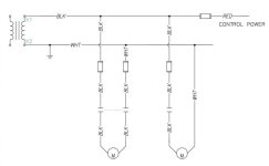
The way I interpret that is that your motor power leads should be black. If one leg is grounded at the transformer then it is a neutral and that leg should be white. If it is not grounded then it is not a neutral and should be black. If that leg is switched then the switched conductor is no longer a neutral. Meaning that you use black wires between the contactor and the motor, while upstream of the contactor you use a black and white wire if the leg is is a true neutral and is unfused.

The colors are to signal you that the wire may have a non-ground potential. That is why you would not use a white conductor between the relay and the motor or if the leg is fused.

EDIT TO ADD a picture for clarity. Disclaimer, this is not advocating a particular single phase motor control circuit, its just an example of how to select wire colors in different single phase motor control scenarios.
8111401.jpg
 
Last edited:

Similar Topics

Kindly, has anyone tried to control Lenze servomotors with Siemens S120 drives ? Any special hints ? Have some concerns for the resolver and servo...
Replies
5
Views
237
Guys its been awhile since Ive posted on the forum... Im looking for a device to control motor speed of a 120vac single phase pump using 4- 20ma...
Replies
19
Views
6,470
We have a couple of S120 drives which are rack pinion system,which moves forward and back ward (linear motion only) . The drive shows Fault 7900 3...
Replies
19
Views
4,342
Hey All, I am looking for help with configuring s120 double motor modules for the following motors. SEW motors (X2)...
Replies
5
Views
2,270
Hello all, I am using a Sinamics G120 CP 240E-2 PN-F control unit to drive a Siemens 1LE10030DA222AB4 3-phase 1hp (0.75kW) motor. The motor has a...
Replies
3
Views
5,096
Back
Top Bottom