1734-VHSC5 Module 2

Tomo453

Lifetime Supporting Member
Join Date
Mar 2018
Location
Mt. Juliet, TN
Posts
83
Hello, awhile back I installed a 1734VHSC5 using the two module setup to ease the wiring to the input module (non-contact laser encoder). I have been tasked to add a second VHSC for a rotary encoder in the same remote I/O rack. My questions are can this second VSHC use the original module 2, and can the second counter be a 24VDC module?
 
This is a great question; the 1734-VHSC5 and -VHSC24 are not commonly-used modules and have an unusual wiring scheme.

Make sure you get both the Installation Instructions (1734-IN003) and the User Manual (1734-UM003) for these modules. There is also a good FAQ in the Knowledgebase (document QA49944, Access Level Everyone).

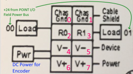
Are you using any of the connections on the Module 2 that is included with a -VHSC ? That module is just a bunch of jumpers on a PC board, and routes the backplane signals to terminal blocks. Those terminals include a chassis ground, the DC common "RET" terminals for the two onboard Outputs, and two terminals each marked "V aux". So in general, everything that the "Module 2" jumpers connections for is accessible elsewhere in the cabinet.

>can the second counter be a 24V DC module ?

Yes, you can put a VHSC24 right next to a VHSC5, omitting the "Module 2" for either or both of them.
 
Last edited:
Clarification for above.

I misunderstood the function of the "V Aux" terminals on the "Module 2" of a 1734-VHSC5 or -VHSC24.

Those do not give you access to the Field Power bus of the POINT I/O assembly.

Instead, they are merely jumpered together left and right: Terminal 4 is jumpered internally to Terminal 5, and Terminal 6 is jumpered internally to Terminal 7.

That gives you the ability to provide your own power to Terminals 4 and 5 (5V or 12V or 24V, whatever), then connect your encoder power leads to Terminals 6 and 7.

There is a wiring diagram printed on the side of Module 2, and an explanation in the Knowledgebase and on Page 2-1 of the User Manual.
 
Last edited:
Okay I'm going to stop ninja editing now. It was a 4 AM, cold-coffee sort of Monday.

Thanks Ken this helps considerably. The second module had me confused. The encoder connected to the VHSC5 counter uses this module to get its power supply from a Non-Contact Laser encoder header. There is a power adapter in this rack just a few slots away. I will use this 24VDC power for the encoder connected to the IK module, eliminating the need for another secondary module(not much DIN rail left exposed here). I will still probably use the Chassis ground access of the original secondary module to save some wiring hassle. I do not like microwaved coffee, so sometimes cold it is.
 
Last edited:

Similar Topics

K
Howdy, I am programming a machine using an AB Micrologix 1500 and AB DeviceNet 1734-VHSC5 Very High Speed Counter Modules to communicate to...
Replies
3
Views
7,887
Looking at installing point io, with a 1734-AENTR communications adapter and ten 1734-IT2L modules. In IAB it installs a 1734-EP24DC after every...
Replies
1
Views
63
Hi everyone, new to forum. Since very long time i having issue with 1734-AENT module, after some period of time its keep stuck in error (simmilar...
Replies
16
Views
628
I am trying to use the 4-20 mA signals from a device whose user manual says that it outputs "isolated 4-20 mA". I only have spare PLC inputs in a...
Replies
3
Views
235
Hello The plant is running and there is no shutdown nowadays therefore I can add 1734- AENTR and its card while PLC is in Run? I do not wanna...
Replies
8
Views
353
Back
Top Bottom